This thread has been locked.

If you have a related question, please click the "Ask a related question" button in the top right corner. The newly created question will be automatically linked to this question.

TPS561201: TPS561201 Over- / Undershoot

Part Number: TPS561201

Hi everybody,

im using the TPS561201 in a new design, but unfortunately i have an issue i can't solve by myself.
I need the converter to bring 500 mA at 5V. Most of the time it will be at light load, only supplying my MCU.

Testing the circuit i found the TPS over- and undershooting. It also affects the 12V-Supply.

This is the schematic i'm using right behind a Recom Rac AC/DC-module :

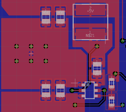
This is what the layout looks like:

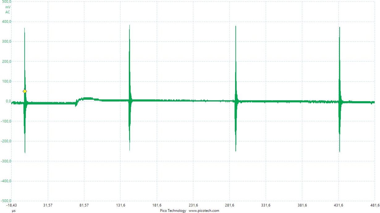
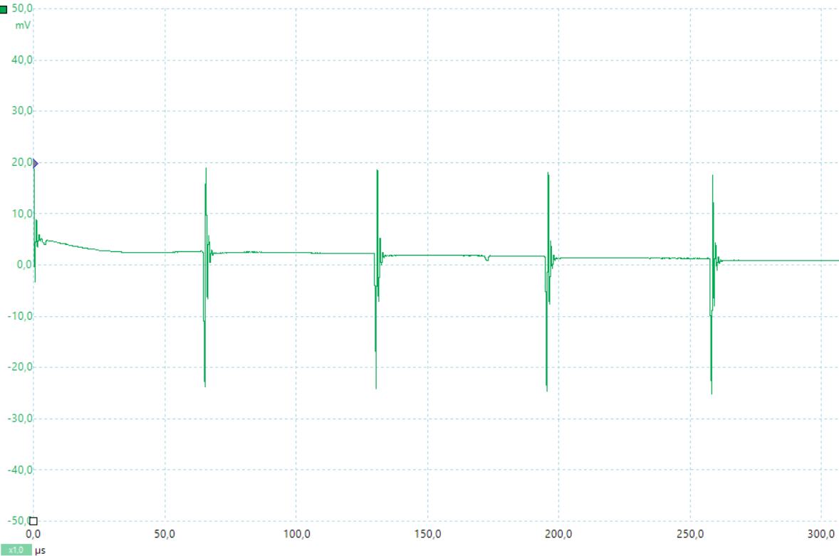
This are the peaks measured on the 12V supply, which change in frequency:

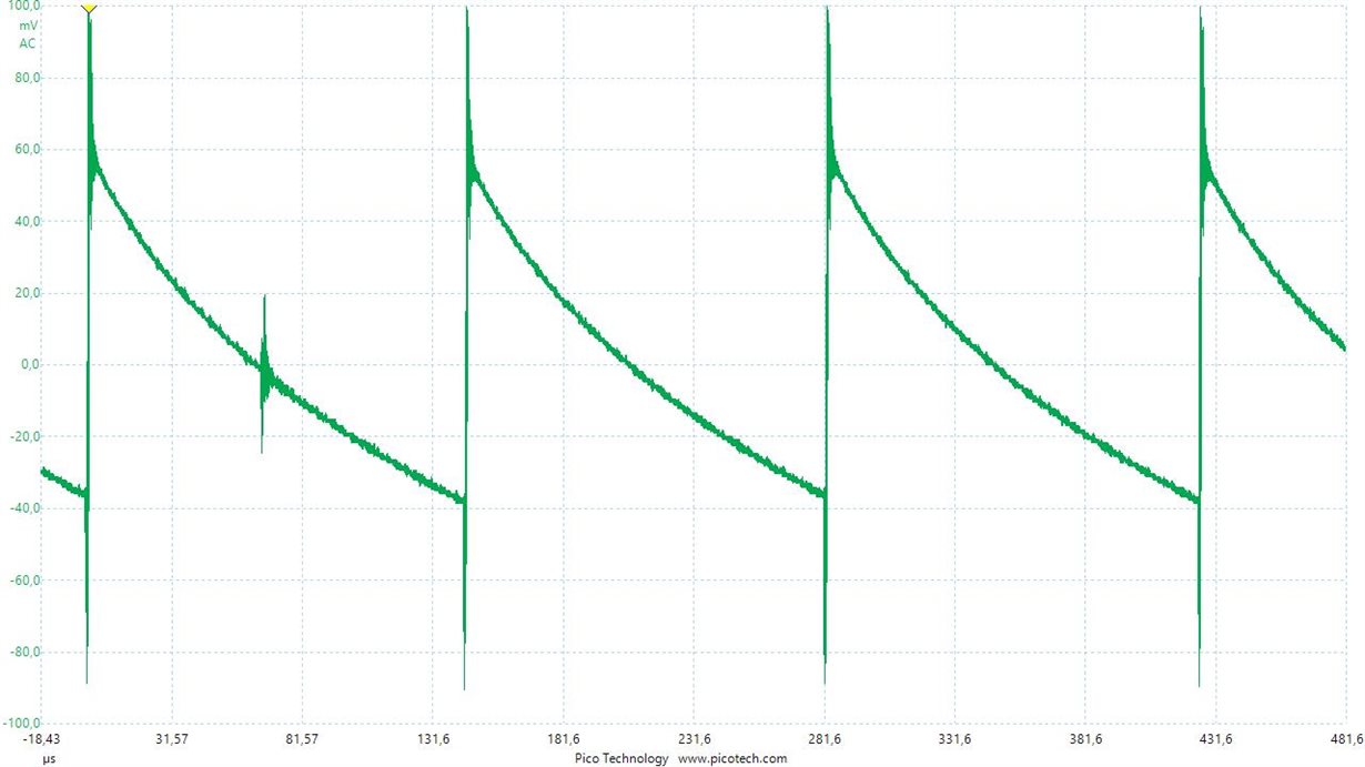
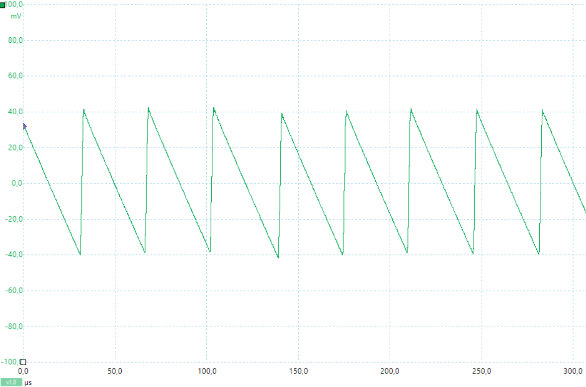
This is what i measure on 5V at DC/DC output:

Adding a 100µF Elko at 5V output  to reduce ripple as test deliveres this:

These measures were all done at almost no load. Putting a restistor the 5V output results in higher frequency of the peaks.

As the inductor the VLS6045EX-4R7M is used.

This problem in reproduceable on an other board with the same layout but without any other parts on it.

I just don't get were the peaks are coming from and really need a solution for this.

Thanks in advance for your help!

  • As I see now the media files didn't attach. So here another try.

    This is the schematic i'm using right behind a Recom Rac AC/DC-module :

    This is what the layout looks like:

    This is what i measure on 5V at DC/DC output:

    Adding a 100µF Elko at 5V output  to reduce ripple as test deliveres this:

  • Hi,

    For the layout, the wire of SW Pin is too thin, and there is only a via, SW is the power stage, this layout is unacceptable. Please refer to the EVM layout as below.
    www.ti.com/.../slvub34.pdf

    For the output ripple, there is too much switch noise on the waveform, it is not the real ripple. You'd better set the bandwidth to 20MHz to test the ripple, and let the loop of probe shorter.

    Shawn
  • Hi Shawn,

    thank you for pointing out my mistake.
    I redesigned the layout and will post an update as soon as its tested.

  • Hi,

    now I got the new PCB. I made the SW-trace wider and the over- & undershooting got better, but it still does.

    The peaks are about 50 mVpp on the input side. About 100 mVpp when I disconnect my 1000µF buffer-capacitor.

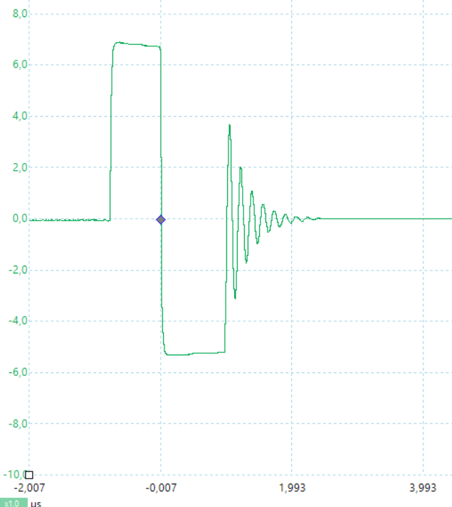
    In addition I measured the SW-Trace and this is what I found:

    This doesnt seem right according to the TPS561201 EVM page 7. May I have a problem with parasitic inductivity on the input?

    As you may have noticed I'm quite unexperienced, so I need to rely on your help with this.

    Thank you in advance!

  • Hi Joe,

    I think this waveform is reasonable, I guess you set the "couple" of the probe to AC, there is 5V offset, please set it to DC. And this waveform is can be seen at DCM, the ringing is caused by the parasitic inductance and capacitance. If you increase the load current, there will be no ringing.

    For the input and output ripple, Could you please share the waveform? I think there are too much switch noise on the waveform as the attached waveform. I suggest you test the ripple by differential probe or ground loop as I mentioned.

    Shawn
  • Hi Shawn,

    I did a new measurement of the input and output. I kept probes GND-trace as short as possible as we have no differntial probe.
    This is the best I could get by enhancing the Picoscopes resolution from 8 bit to 12 bit.

    This are the peaks on the 12V input which got a lot smaller compared with the first design. The waveform was measured in standby opertion of the circuit. Adding load to the 5V output doesn't influence the height of the peaks but just the frequency. I would like to get rid of them.

    On the 5V output I measure a ripple of about 80mVpp at light load, which is a little more then I expected it to be.

    As always I thank you for your help.

  • Hi Joe,

    Form the output ripple waveform, it was tested under light load, the device works under Eco-mode, the ripple is larger than CCM mode, you can test it with 1A load.

    Shawn