This thread has been locked.

If you have a related question, please click the "Ask a related question" button in the top right corner. The newly created question will be automatically linked to this question.

TPS65251: Behavior in cold temperature

Part Number: TPS65251

Hello, 

I have a question about thermal performance for the TPS65251. 

We have measured spur performance at the output 1 of the TPS65251 eval. board.  Input voltage was 10.2V, output voltage was set to 6.2V. Output current 1.59A (3.9Ohm resistor as a load) and switching freq. 500kHz.

this is measured spurs at the output 1 of the regulator vs temperature (inside the thermal chamber):

spur freq., kHz power, dBm
+20C 0C -20C -25C -30C -40C *
167 -54 -54 -55 -54 -54 -55
261 - - -25 -23 -21 -19
522 -27 -27 -27 -27 -27 -29
784 - - -39 -39 -37 -39

*unstable 

so only two spurs (167kHz and 522kHz - switching freq.) are presented at the regulator output when the temperature higher than 0C. But for -20C and lower there are two additional spurs appear - 261kHz and 784kHz, and for the temperature -40C output voltage became unstable.

Is it normal behavior for TPS65251?

Is there official information about the operation of the regulator in cold temperature?

Thank you!

  • Hi,

    We don't have spur performance data versus temperature.

    Can you post your schematic here? Do you have the unstable Vout waveform at -40C?

    Or you can contact me by email. My email address is sam.zhang@ti.com

    Thanks.

    Regards,

    Sam

  • Hi Sam, 

    Thank you for the reply!

    We use TPS65251EVM with only one modification - R12 replaced by 5.97kOhm (in order to have 6.2V output voltage). 

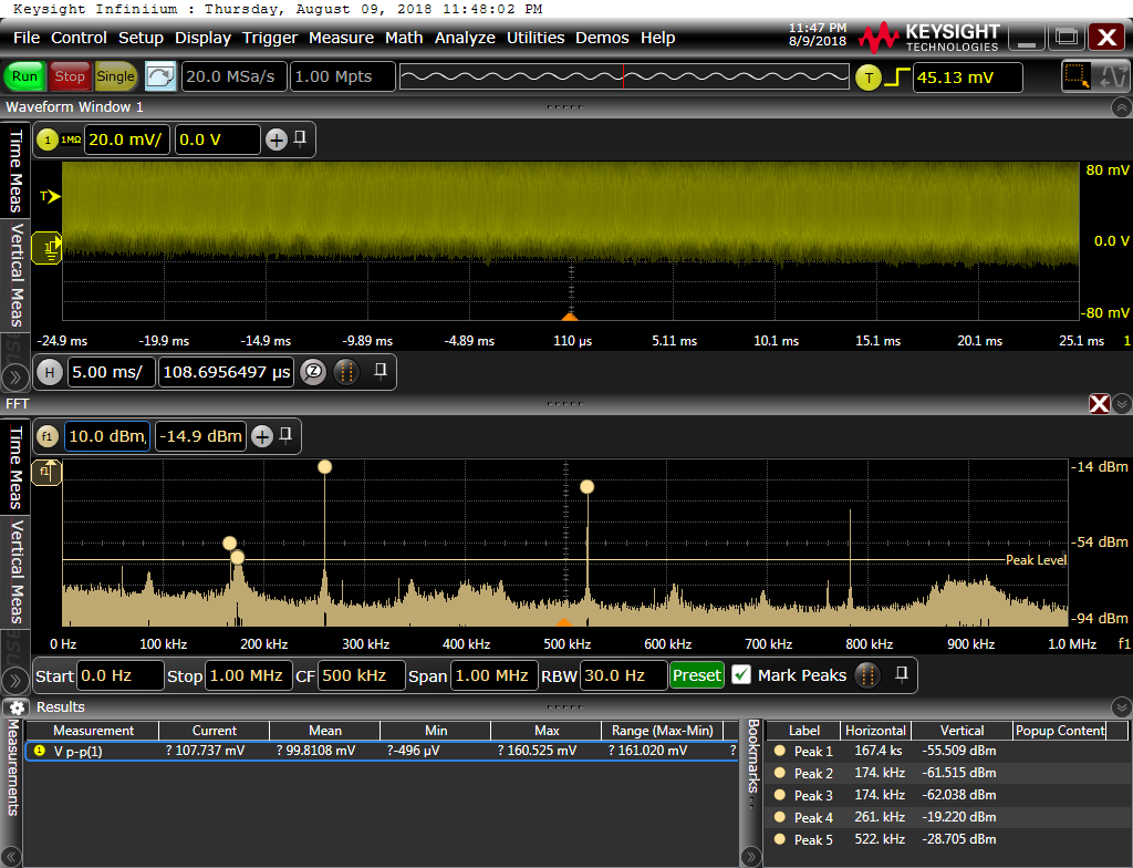
    this is the oscillograph screenshot for -40C (AC coupled): 

    also, the level of the output voltage drops with a very low frequency. (1 Hz or lower), and then returns to the initial state. You can see on the screenshot that waveform is not stabilized.

    Regards,

    Sergey

  • Hi Sergey,

    As the Vin is 10.2V, and Vout is 6.2V in your application, the inductor current ripple is calculated to be ~1.03A. It's too large compared with your loading(1.59A). Internal slope compensation may not support this. So, I'm suspecting if it can cause the sub-harmonic oscillation issue. 

    Can you zoom in the output ripple when the instability happens? You may try to use a 10uH inductor in your application.

    Thanks!

    Regards,

    Sam

  • Hi Sam,

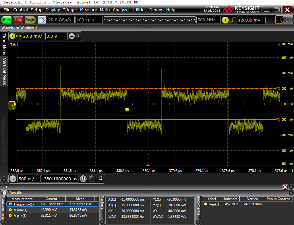
    this is output waveform for instability case (4.7uH and -40C):

    Then we replace 4.7uH inductor with 13.6uH and subharmonics are disappeared. Now it's the only 167kHz and 522kHz. Also, there is no instability case, even for -50C, it's only this two spurs. 

    this is new waveform: 

    So, you right, it looks like the instability cause was subharmonics.

    Can you also help with this 167kHz spur, do you know the source and what we can do to decrease or move it?

    Regards,

    Sergey

  • Hi Sergey,

    First of all we need to know where it comes from. Change some parameters, such as output capacitance(22uF to 44uF or 68uF), and then, see if the spur frequency has changed. You may also change the CFF (the capacitor put in parallel with RFB_top).

    BTW,

    1. Please note that -50C has exceeded the operating temperature range.

    2. Actual output ripple is much smaller than your test result in the last figure. Obviously the SW waveform is coupled on the Vout probe. 

    About how to measure the Vout ripple, you can take this reference,

    e2e.ti.com/.../how-you-measure-your-ripple-can-make-you-or-break-you

    Regards,

    Sam

  • Hi Sam,

    Thank you!

    regarding -50C it's just to show that there is no this issue with subharmonics even for such low temperature.
    We measure ripples using pigtail method and of course, it's much better comparing to clip-on method

    Regards,
    Sergey