This thread has been locked.

If you have a related question, please click the "Ask a related question" button in the top right corner. The newly created question will be automatically linked to this question.

WEBENCH® Tools/TPS63710: Power Supply

Part Number: TPS63710

Tool/software: WEBENCH® Design Tools

Hello,

I am making a 12-14 V input, -2.5V output switching power supply. It should use .1A current. Please see the schematic below. Still have much too much ripple on the output. Should I up the inductor and C01/C2 values? COuld you give me specific values for the inductor and C01/C2 that would have a lower ripple?

Thanks,

Sarah C

  • Hello Sarah,

    Is it a simulation result or do you have measurements in a real circuit? How much ripple do you get on the output, and what is your goal?

    You can find the design guidelines for sizing the elements in the datasheet. Your schematic looks fine, and the ripple should be in the order of mV.

    Could you please show the PCB layout if you are using a real circuit?

    Best regards,
    Milos
  • Hello,

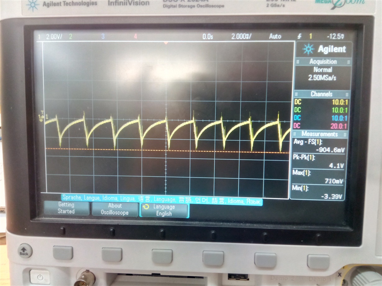
    The pcb is below. The left side is a positive power supply that's unrelated. Below this is a measurement using oscilloscope.  I attempted changing out the two cout caps (C2 and C0) and adding a load resistor of 25 ohm but this didn't really help.

    Thanks,

    Sarah C

    You can see below initially a oscilloscope pic using the schematic sent:

  • Hello Sarah,

    A ripple of this size and frequency indicates that there is a serious issue with the circuit. In this case the problem is most likely the PCB layout.

    Please take a look at the layout guidelines in the datasheet, page 25. You should appropriately size the traces, make a good ground layout, and place the filtering elements as close as possible (electrically!) to the regulator. These are some of the general rules when making a PCB for any switch-mode converter. I recommend the following guides as the starting point:
    Layout Guidelines for Switching Power Supplies
    Five Steps to a Good PCB Layout of a Boost Converter
    Five steps to a great PCB layout for a step-down converter

    Or you can just copy the recommended layout from the datasheet, with minimal changes.

    I suspect there is a linear regulator on the left, so the same applies there.

    Best regards,
    Milos

  • Hello,
    My pcb is very similar to the datasheet. I did exchange the inductor and output capacitors to get things closer to each other for my next iteration and Im going to try a larger inductor. I am thinking the issue may be that there is no power and ground plane, so there are more long circuitous traces. Could this be the issue?
  • Hello Sarah,

    Your PCB is topologically similar to the recommended one, but that is not enough. Your trace widths are inadequate and the ground routing should be improved. Merely connecting the components is not enough, and changing the component values will not help. That is why I was referring to the recommended layout in the datasheet.

    Best regards,
    Milos
  • Ok, here is my first draft. I added a power plane and ground plane and made the traces thicker. I am also going to try to make one with the polygon tool. But let me knoe if you think this one will be good. The right side is the circuit I showed you prior.

  • Hello Sarah,

    The arrangement of the components is better now, however, you should still make the traces wider, as wide as your layout allows. Especially the traces between the input and output capacitors and VIN, SW and CP pins. The input and output capacitors should be placed even closer to the TPS63710, and Cix1 should be the closest one to the device. For better ground connection place vias below the device and connect both GND pins to it, just like in the datasheet example. and the ground side of the output capacitors can be directly connected to the TPS63710 ground on the top layer.

    The recommended layout in the datasheet accomplishes all of the above mentioned requirements in only two layers.

    Best regards,
    Milos
  • Hello Sarah,

    We haven’t heard back so we're assuming you were able to resolve your issue. If not, just post a reply below, or create a new thread if the thread has locked due to time-out.

    Thanks and regards,
    Milos