This thread has been locked.

If you have a related question, please click the "Ask a related question" button in the top right corner. The newly created question will be automatically linked to this question.

Buck / Boost Converter Design for very high currents

Other Parts Discussed in Thread: TPS40140, UCC27321, TPS40090, UCC39002, CSD17307Q5A

Dear Sirs / Madams,

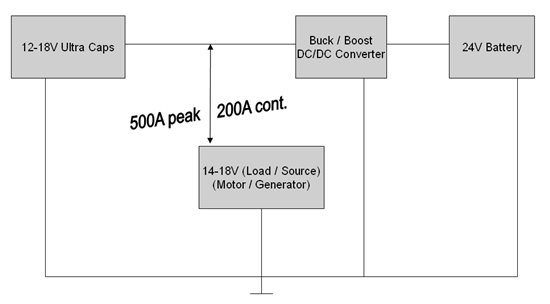
We'd like to find out whether TI offers an integrated circuit that allows us to build a DC/DC converter for both directions (buck direction from 9-18V --> 24V, and Boost from 18-24V ----> 9-18V). It's an application where both sides of the converter will be battery powered.

The low-voltage side will be powered by a 12V battery system but this side also offers up to 200A (@18V) for short periods (buck mode request) which should be used to load the 24V system....

The high-voltage side will be powered by a 24V battery and has to support the low-voltage side with up to 18V / 500A for very short periods only  500ms-1sec (boost mode request). Mostly the high-voltage side will boost the lower side with a max of. 200A (@14V) which should be realized for a longer period or almost continuously.

We're not afraid of "stacking" or putting many devices in parallel.


Thanks for your appreciated suggestions!

  • Tom,


    I think you have your BOOST and BUCK converters back.

    A BOOST converter takes in a low input (Like your 12V battery) and outputs a higher output voltage (18V)

    A BUCK converter takes in a higher input voltage (like your 24V battery) and outputs a lower voltage (18V)

    For a 24V to 18V 500A capable converter, I would have to recommend the TPS40140, though running it with an 18V output will require shunt monitors to level shift the sensed output current to a ground referenced voltage for the current sense amplifier.  I recommend the TPS40140 controller because this controller is designed to support stacking with upto 16 deperate time divisions, allowing you to combine many lower current phases to produce your final 500A load.  This comes to about 32A / phase.

    The BOOST will be slightly more difficult as TI doesn't offer a stackable controller that can support a Boost power stage.  I would recommend using the TPS40090 4-phase driverless controller here with 4 of TI's high current UCC27321 9A MOSFET drivers.  18V @ 200A will draw about 300A from a 12V input, needing 75A of switch current in each of 4 phases, so it might be desirable to use more controllers with the UCC39002 load share controller to ensure they contribute equally to the final output.  My recommendation here would be 2-3 TPS40090 controlled boost power stages for 25-35A / phase.

  • Hello Peter,

    thank you very much for your advice. I am not sure how to combine the different devices within one design. Is is possible for you to draw an architecture overview to show how to combine the modules. Also I'd nee to know how to switch between the operational modes (buck / boost). I'd prefer to use a microcontroller system I am familiar with, is that possible?

    thank you very much in advance.

  • Tom,


    Let's start by making sure we're both thinking about the same power problem first:

    My understanding is you have an 18V load that needs to be able to draw power selectively from a 12V battery or a 24V battery in 200-500A pulses between 500ms and 1s in length.  Based on that understanding, I proposed this possible solution:

    Please correct me if this seems like your desired power configuration.  Also, if you can send me a private message with your company, location, project and end equipment application, I'd like to see if we can get you in touch with some of TI's local field support to offer there help as well.


  • Peter,


    actually the topology is a little bit different. Can you imagine which device should probably work out for us? Thanks!


  • Tom,

    Thank you very much for the explination and clearification.

    I have some very good news for your application - A synchronous BUCK power stage will function as a synchronous BOOST Power Stage when the voltage on the output is greater than the target output voltage as long as the controller is able able to handle this configuration and the TPS40140 controller is able to do so.

    If you build a 24V 16-phase synchronous Buck converter with programmable output voltage (or current) to drive your motor and the current needed to maintain that voltage on the motor becomes negative (such as when the motor begins generating power) the BUCK converter will begin drawing current from the motor/generator and forcing it into the battery.

    I don't know the perticulars of your application's control mechanism, but I will start with a Current driven system as its easier to explain.


    You would design a TPS40140 based 16-phase converter, but instead of feeding back the output voltage, you'd feed back a voltage proportional to the motor/generator current plus an offset.  - The offset is used to allow the current to be Positive or Negative.

    When the sensed current needed to get 0.7V at the FB pin is positive, the control loop will force the power stage to operate as a BUCK, driving current into the motor.

    When the sensed current needed to get 0.7V at the FB pin is negative, the control loop will force the power stage to operate as a BOOST, drawing current out of the generator

    The micro-controller can then make adjustments to this feedback circuit to select the mode of operation for the converter.


    In a voltage driven system, the micro-controller would still adjust the feedback, programming an output voltage below the natural electro-motive force of the generator to drawn energy from the generator or above the natural electro-motive force of the generator to force energy into the generator.  Which to use will depend on your motor control scheme.  Whether it's current or voltage driven.

  • Hello Peter,

    your answer sounds amazing positive! The project I am applying for request an A-sample of this converter-system by beginning of April. I would appreciate detailed advice in terms of component selection, sample schematic and architecture of the stack-design already available.

    thank you so much!

  • Peter,

    due to the very short development phase I though about using the the TPS40140EVM-003 evaluation module (EVM) in a stacked configuration of 8 Boards to build the first prototype converter. The assembled MOSFETs are 25V Vds types which should be replaced by CSD17307Q5A (30V / 73A). Also some of the resistors need to be replaced to setup for 14-18V but basically we could focus on implementing the interface to the microcontroller only.

    Do you consider this idea feasible?

    Thanks for your advice.

  • Tom,

    There are a couple of possible issues with this:


    1) A 30V MOSFET is likely not the best choice for a 24V input.  Ringing on the switching node will likely result in more than 30V applied to the Drain-Source voltage of the low-side FET.  I would encourage you to consider a 40V MOSFET for a 24V input.  TI does not currently offer 40V MOSFETs.  I have worked with Infineons MOSFETs before and found them to have the best performance when TI NexFETs are not available for the desired voltage range.

    2) The Output Capacitors on the TPS40140EVM-003 evaluation module are not able to support 18V output.  The 330uF specialty polymer capacitors are only 2.0V rated capactiors while the ceramic capacitors are only rated to 6.3V

    3) The TPS40140EVM-003 evaluation module uses direct DCR current sensing, which can only support output voltages upto 5.5V due to the common mode range of the TPS40140 current sense amplifier (CS+ and CS-)  This why why I recommended a Current Shunt Monitor to level shift the sensed current to the common mode range of the current sense amplifiers.  Adding these monitors would require significant rework.

    4) With the change in the output capacitors and the current sense network, you'll want to review the loop compensation to make sure its still stable.


    You'll need to make significant PCB changes to convert 8 TPS40140EVM-003 PCBs to your application.