This thread has been locked.

If you have a related question, please click the "Ask a related question" button in the top right corner. The newly created question will be automatically linked to this question.

Powering the AM335x with the TPS650250 in the Power Save Mode

Other Parts Discussed in Thread: TPS650250

Our customer has the issue: http://e2e.ti.com/support/arm/sitara_arm/f/791/t/367724.aspx

For the power design, they referred to User's Guide: http://www.ti.com/lit/ug/slvu731a/slvu731a.pdf

The power mode setting is set to the Power Save Mode (MODE=Low) in the customer board, but it is set to the forced PWM Mode (MODE=High) in the User's Guide.

Has it been tried that the TPS650250 in the Power Save Mode works for the AM335x by TI? Is there not any information?

Best regards,

Daisuke


  • Hi Daisuke,

    My belief is that the application designer was concerned about higher ripple being present on any/one rail of the Sitara. In the Power Save Mode, (MODE = 0), the switching frequency is decreased to save switching power in order to increase light load efficiency.  As a result, the ripple voltage on the output is higher than when forced PWM mode, (MODE = 1), is enabled.

    The other concern is that the Sitara demands +/- 4% accuracy with load transients' AC performance taken into account as well. The forced PWM mode will yield better DC regulation and provide more margin for transient response AC performance. By enabling power save mode, the power supply might violate the +/-4% requirement.

    I recommend experimenting with power save mode while powering the Sitara and evaluate the Sitara performance for undesired effects.

  • Hi Michael,

    Thank you for your reply.

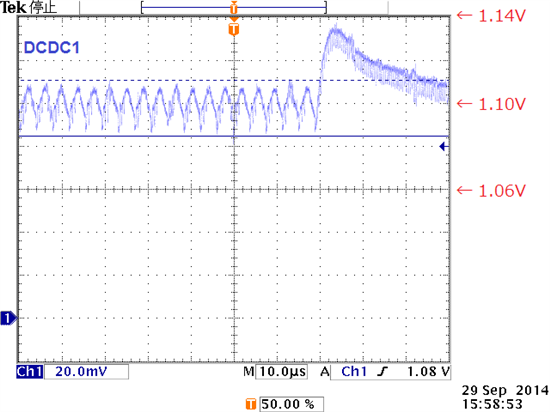
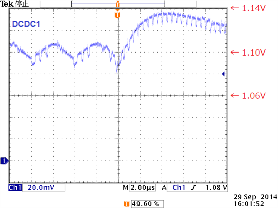
    The customer checked a ripple and a load transient phenomenon in power save mode. The DCDC1 output does not seem to be beyond the +/-4% recommended voltage range of AM335x.


    Best regards,

    Daisuke


  • The datasheet specs across corners and temperature. It is your call on your comfortableness of the lab results.

  • Hi Michael,
     
    Thank you for your reply.

    When the DCDC1 output voltage is increased to 1.110V, all failed boards seem to work correctly.

    Our customer is investigating when the DCDC1 voltage drops below the recommended minimum voltage.

    Best regards,
     
    Daisuke


  • It looks like it is on the insertion of a current transient that causes a voltage droop. Can you take a scope shot of the transient with a zoom in on the voltage droop? (ILoad goes from low to high)

  • Hi Michael,

    Thank you for your reply. Sorry for my late reply.

    Our customer cannot confirm that a voltage drops below the recommended minimum voltage. They are going to be supported by our local TI.

    I am grateful for your cooperation.

    Best regards,

    Daisuke