This thread has been locked.

If you have a related question, please click the "Ask a related question" button in the top right corner. The newly created question will be automatically linked to this question.

TPS65217 Interface

Hello,

I have a question about the operation of the TPS65217C PMIC. From what I have gathered, the device immediately powers up the LDO1 rail, which is used for the VRTC voltage when interfacing to the AM335x series. The SYS_5V also immediately is connected to the input power. The VRTC rail controls the RTC_PORZn pin of the AM335x processor, which then starts the power-up sequence of the processor. After the RTC stabilizes, the processor launches the rest of the power-up process by activating the PMIC_POWER_EN signal.

From reading the datasheet, it appears that the default operating condition for the other 3 LDOs as well as the 3 switcher outputs is in the off state. I2C is required to enable these signals, but the peripherals of the AM335x require voltage from one of the outputs that is disabled, so it seems to me that there is a chicken and the egg situation there. I'm sure I am interpreting something incorrectly and would appreciate a detailed response on how the power-up is handled.

To attempt to test this device prior to using it on a much larger design, I made a PCB with the reference design on the Beagle Bone Black board (minus the AM335x processor) and tried to test the IC. Upon powering on, the SYS_5V oscillates between 3.11 and 4.0 V, the current draw ranges from 1 mA to occasional spurts at 12 mA and the LDO1 rail oscillates between 0V 0.33V and 0.65V. I'm not really sure what to make of this. It seems that the only input that the power-up is reliant on the is the PMIC_POWER_EN, so it seems like tying it high would cause the system to power up.

Could you please enlighten me on my mis-interpretations and oversights?


Thanks.

  • Tony,
    To address your first question, the register default values are set for at time = 0, this is before the sequencer has started, therefore they are all disabled. After a wakeup event the sequencer is started and enables the power resources. The input power up is reliant on the Power enable being pulled high within 5s of a wake up event (AC applied, USB applied, or Push button pressed, and no faults detected). When you say that you made your PCB reference design with the BBB minus the AM335x processor, do you mean you just don’t have a processor or you are using another processor? Would it be possible to see your design?
    Janice
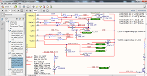
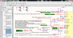
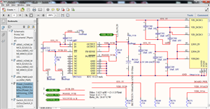
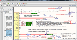
  • So the main difference between this diagram and the test board is that the PMIC_PGOOD, LDO_PGOOD, WAKEUP, and PMIC_INT outputs do not go to a processor and are instead test points. Also, the PMIC_PWR_EN does not go to the AM335x, but is pulled high to the SYS_5V rail. I have measured this input and it tracks the SYS_5V as it should. The issue is that the SYS_5V output is not stable and varies from 3 to 4V, an issue I cannot make sense of. The I2C lines are not connected either. It seems that according to your input the device should power up as long as PWR_EN is pulled high. Please let me know if the attachments that I provided are too difficult to read.

  • Tony,

    Where is the 2.2uF output cap on VLDO1 (pin 3)?


    Janice

  • In the top screenshot that I sent you (showing the lower right portion of the schematic block), it is connected to VRTC. However, since I had limited space, it is off to the right side where the 3 parallel green boxes show VRTC, VDDS, and VDD_3V3AUX. It is capacitor C208.
  • Tony,
    This could be due to a layout issue, like the caps not being close enough to stabilize the LDO, but that's hard for me to tell? Are you getting any faults, like PGOOD going low? Have you looked at our EVM for this part, would you like me to send you one so you can evaluate the part?
  • PGOOD never goes high, which I would expect due to LDO1 never going high, which indicates a fault. It would be great to evaluate the part with the EVM. The layout for this board could potentially be an issue. It is much more tightly arranged in the actual design than this test board, so we could be running into issues there. I can try to add capacitance closer to the IC in the meantime to see if this stabilizes anything.
  • is 2.2uF required? i was going to select a different value....thanks
  •  

    Mark,


    For what? Just because it is on the EVM doesn't mean it is required, I would check the data sheet for recommended parts, they have multiple values and parts that are interchangeable.


    Janice

  • the question was in regards to the comment you made, "Where is the 2.2uF output cap on VLDO1 (pin 3)?" I read that comment and thought that there might be a specific component requirement driving the selection... If you are saying that the value selection is dependent on the design for my system then i am good.... thanks