This thread has been locked.

If you have a related question, please click the "Ask a related question" button in the top right corner. The newly created question will be automatically linked to this question.

TPS65051 start up time issue

Hi,

Can anyone help to resolve the start up time issue of TPS65051RSMT.

As per the datasheet  the maximum start up time for the LDO's is120uSec.But  measured value is 12mS.

Please find attached file's for wave forms and schematics and let us know if any modifications required.

Rgds,

UmaMahesh

PMIC.PDFWave forms.docx

  • Hi, 

    The start up could be limited by your input supply. Check you supply is not hitting max supply current on start up. If the supply current is ample then, hold EN low until the VIN ramps up and is steady-state. Assert EN high and recapture the waveforms' start up.


    Check if the slow start is on all of the LDOs or just one. Remove the inductor filter and shorting resistors to separate the PMIC from the load check the LDO rails' start up then. If the time reduces significantly then you should check your loading circuit and capacitance.

    Also, please note that the LDO maximum tart up time is not specified and can depend on the circuit application and loading capacitance. The waveforms in the datasheet are typical characteristics and I recommend having only 2.2uF for output capacitance for your measurement comparison.

  • Hello Michael,

    The startup could be limited by your input supply. Check you supply is not hitting max supply current on start up. If the supply current is ample then, hold EN low until the VIN ramps up and is steady-state. Assert EN high and recapture the waveforms' start up.

    Response:we are testing the PMIC with below scenario

    Input supply for PMIC is from external DC/DC supply (from Aplab) which is set at 3.9V and current limit set max limit (i.e. 2A)

    Once 3.9V reached the steady state then only connecting PMIC input to this supply rail.

    Hence above scenario of start time limitation by input supply not holds good.

    Check if the slow start is on all of the LDOs or just one. Remove the inductor filter and shorting resistors to separate the PMIC from the load check the LDO rails' start up then. If the time reduces significantly then you should check your loading circuit and capacitance.

    Responce:Start up time problem applicable for all LDO's.

    Tried with removing inductor filter & isolated all loads from the   supply rail.But  no improvement.

    Also, please note that the LDO maximum tart up time is not specified and can depend on the circuit application and loading capacitance. The waveforms in the datasheet are typical characteristics and I recommend having only 2.2uF for output capacitance for your measurement comparison.

    Response:Above condition also tried by removing all other capacitance at the output of LDO (Retaining only 2.2uF),But no improvement.

    Attached few snapshots for your reference.

  • Hi Michael,

    we are testing the PMIC with below scenario

    Input supply for PMIC is from external DC/DC supply (from Aplab) which is set at 3.9V and current limit set max limit (i.e. 2A)

    Once 3.9V reached the steady state then only connecting PMIC input to this supply rail.

    Hence above scenario of start time limitation by input supply not holds good.

    Start up time problem applicable for all LDO's.

    Tried with removing inductor filter & isolated all loads from the   supply rail.But  no improvement.

    Above condition also tried by removing all other capacitance at the output of LDO (Retaining only 2.2uF),But no improvement.

    Attached few snapshots for your reference

  • Hi ,

    Can Anyone help to resolve above issue.

    Rgds,
    Uma mahesh

  • HI,

    Sorry for the delay I am looking into this for you and will try to have an update today on some testing I will do in the lab.
  • Hi Michael,

    Thank you for your reply.

    Rgds,
    umamahesh
  • Hi,

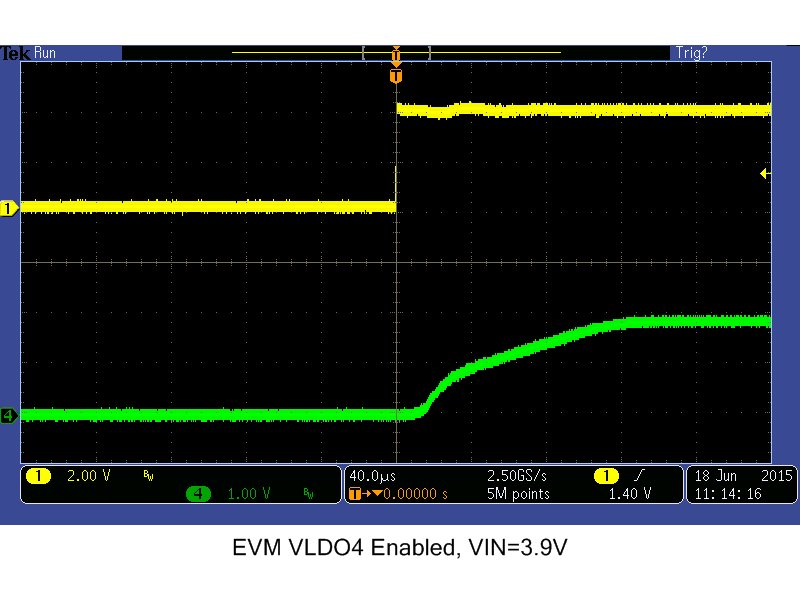
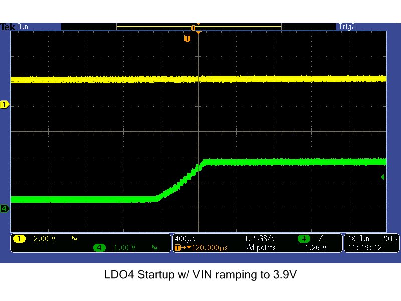
    Can you please post waveforms with the LDO_ENs, VIN ramp up, and the LDO outputs? If the device is allowed to have its VIN ramp up to 3.9V then have the LDOs enabled the start up time is shorter than if the LDOs are always enabled and the LDOs turn on once the device exits UVLO. In this latter case, the LDO start up times can be longer. See images below for example:

  • Hi,

    Pls find attached waveforms FYR.

    Rgds,

    Umamahesh

  • Hi,

    Does this happen on all of your boards? Have you tested this on an EVM? I have been doing some research and testing here to only find that for this device the VIN ramping with LDO and the amount of Cout are currently the only 2 factors for start up time being affected.

    Secondly, is the yellow signal the VIN to the LDO? Could you include the EN signal if not shown already. Please include the BP signal too.

    I see in your schematic that the only GND is DGND. Is there any noise injected on the FB or VCC pins from a possibly noisy digital GND?

    The LDOs should have their references' ramped which in turn controls the softstart ramp time. This would mean that Cout would not affect it but, if the Cout is so high, (possibly our recommended Cout value), that the LDO ramp would be limited by the capacitance on the output instead. To test this theory I will try the LDO with EVM default 10uF then, add 2 x 22uF for ~50uF and finally, try 1 x 0.1uF for Cout.
  • Hi,

    We are working on the evaluation kit you have offered.

    Please find attached file for the  Power sequencing we are following in our design .

    I am observing the 3.3V and 3V waveforms during power up on Oscilloscope . The observed waveform attached ( Blue: 3V and Yellow:3.3V)

    I have observed  3V stabilized earlier compared to 3.3V .But reverse shall happen as per our design.

    Please help to resolve this issue.

    Accord soft.docx

    Rgds,

    UmaMahesh

  • It looks like the VIN would be ramping when the 3.3V is trying to start up. Can you add a delay to the 3.3V LDO or the first DCDC to wait for the VIN to ramp up to nominal voltage before you enable the rails. You can add RC delays to the ENs to pace of the rail sequence.