This thread has been locked.

If you have a related question, please click the "Ask a related question" button in the top right corner. The newly created question will be automatically linked to this question.

TPS65217C connection with AM335X processor for powering up from VBAT(3.6V to 5.5V DC supply) only

Other Parts Discussed in Thread: TPS65217

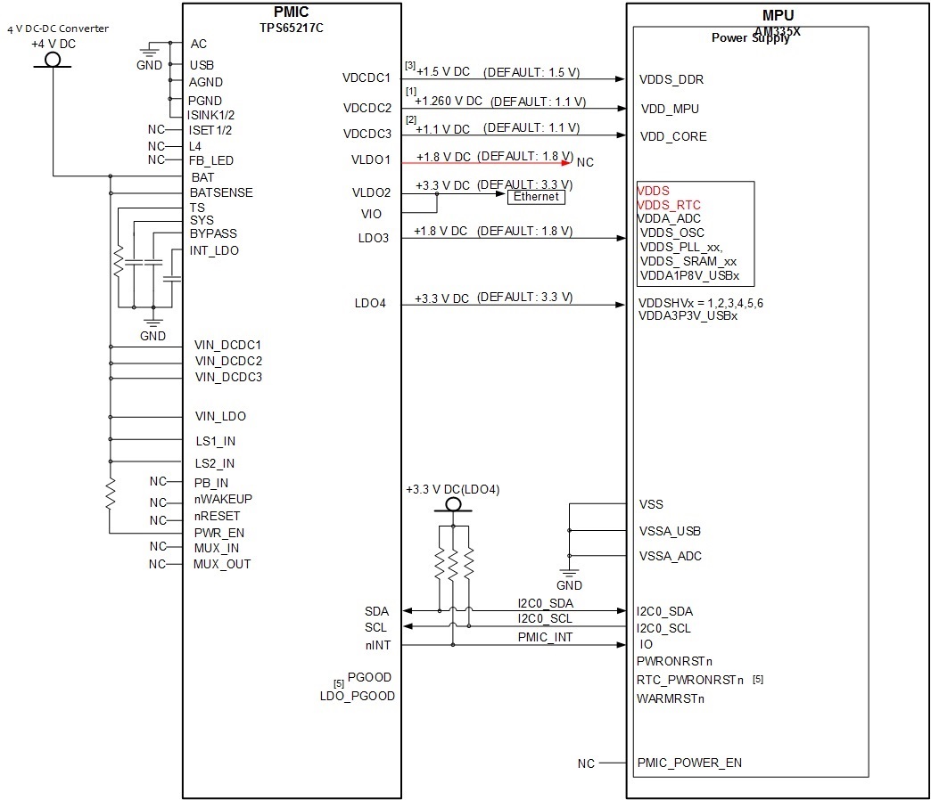
I am using TPS65217C with AM335X for DDR3L(1.5V operation) intreface. I want to power up TPS65217C using VBAT supply (3.6V to 5.5V DC supply from voltage regulator). I am referring the figure 56( right side figure for connection) for powering up from VBat and not providing AC and USB supply (0V). Please let us know if there is  any performance issue or any other issue in generating the voltage output  from powering up from Vbat supply and not using AC and USB supply. I also don't want to used charging functionality and want to disable the same.

  • Hi Manoj,

    The differences in this configuration are detailed in Table 36 (Case 3), just below figure 56.

    The biggest impact is that VLDO1 will not be enabled until the push button is pressed, so please keep this in mind if VLDO1 is supposed to operate as an "always on" LDO in your design. Other than that, there are no performance issues that I'm aware of.
  • HI Rechard.

    I have following query, please reply for the same.
    Senario : I want to power up TPS65217C using VBAT supply (3.6V to 5.5V DC supply from voltage regulator) and not providing AC and USB supply (0V).

    1. Can we provide supply to VDDS, VDDS_RTC of AM335X from LDO3(TPS65217C) as LDO1(whihc is recommended connection for VDDS, VDDS_RTC supply as per user guide) is not on at power on when Vbat is 5V and no low event PB_IN. We are not using PB_IN our design. We are using RTC timer functionality but no RTC-only mode for AM335X.

    2.As per power up sequence diagram in TPS65217C User guide DCDC1(VDDS_DDR) and All other 1.8V supply(VDDS, VDDS_RTC) is coming up with 1ms difference while in AM335X power up sequence in datasheet figure 6-5, it is coming simultaneously. So how TPS65271C is fulfilling power up seqnecunce in RTC timer functionality but no RTC-only mode for AM335X.

    3. What is the power sequence for VBAT 4V input, 0V at USB and AC as per right side figure 65 in TPS65217X datsheet.

    4. Is these(below) pins connection are ok for boot up when we use VBAT 4V input(DC supply), 0V at USB and AC as per right side figure 65. System is not battery operated system.
    PB_IN, Wakeup is floating (We dont require nwakeup as we are not going in sleep mode ), power enable is pulled high to VBAT. Reset is NC.
  • 1. Can we provide supply to VDDS, VDDS_RTC of AM335X from LDO3(TPS65217C) as LDO1(whihc is recommended connection for VDDS, VDDS_RTC supply as per user guide) is not on at power on when Vbat is 5V and no low event PB_IN. We are not using PB_IN our design. We are using RTC timer functionality but no RTC-only mode for AM335X.

    • You may need a push button if you want to use VBAT, or otherwise will have to trick the PMIC into seeing a wakeup event, mentioned in the notes of Figure 20. In Figure 20 you can see that the PMIC will not care about the PMIC_EN until it transitions out of OFF mode, which requires a Wakeup event described in the notes.

    • Why not still use LDO1? Even though Strobe 15 does not start without a wakeup event, it will still occur before LDO3. Since you don't appear to be using the PMIC_POWER_EN, this should be OK, but the notes in the AM335x datasheet mention that ramping VDDS_RTC after the core will cause additional leakage on the core rail.

    2.As per power up sequence diagram in TPS65217C User guide DCDC1(VDDS_DDR) and All other 1.8V supply(VDDS, VDDS_RTC) is coming up with 1ms difference while in AM335X power up sequence in datasheet figure 6-5, it is coming simultaneously. So how TPS65271C is fulfilling power up seqnecunce in RTC timer functionality but no RTC-only mode for AM335X.

    • The 1.8 supplies and the VDDS_DDR supplies are the same for all configurations in the AM335x datasheet (6-2, 6-3, 6-4, 6-5, and 6-6). This 1ms delay is likely for a proper shut-down sequence, where the TPS65217 disables the supplies in the reverse order, and would then disable the 1.8V supply before the VDDS_DDR, as is recommended in the Power-Down section of the AM335x datasheet.

    3. What is the power sequence for VBAT 4V input, 0V at USB and AC as per right side figure 65 in TPS65217X datsheet.

    • The Power sequence will not change, it is defined by the version of the TPS65217x and strobe assignments are not dependent on the input supply. The sequencing is mentioned in the TPS65217x User's Guide, as well as in the datasheet.

    4. Is these(below) pins connection are ok for boot up when we use VBAT 4V input(DC supply), 0V at USB and AC as per right side figure 65. System is not battery operated system.

    PB_IN, Wakeup is floating (We dont require nwakeup as we are not going in sleep mode ), power enable is pulled high to VBAT. Reset is NC.

    • I would not recommend omitting nWakeup or nReset, as I don't know how this will affect the PMIC driver and could limit your design in the future.
  •  Hi Richard,

    Thanks for your earlier inputs.

    PFA our PMIC and AM335X connection for your review for VBAT (DC supply operation)

    . We are using VBAT (DC supply, Its  not battery supply). We dont want to use any push button on PB_IN (As per check list PB_IN can be left floating if not used.)and  not using wakeup signal (it is output signal of PMIC) and pull up(recommended in checklist) at PWR_EN signal.  We want out device to be turned on as soon as it receive VBAT supply(4V to 6V).

    Please provide your valuable suggestion

     We are not sure regarding use of LDO1 to VDDS and VDDS_RTC connection. Currently it is shown to connect on LDO3. 

    Regards

    Manoj A

  • Hi Richard ,

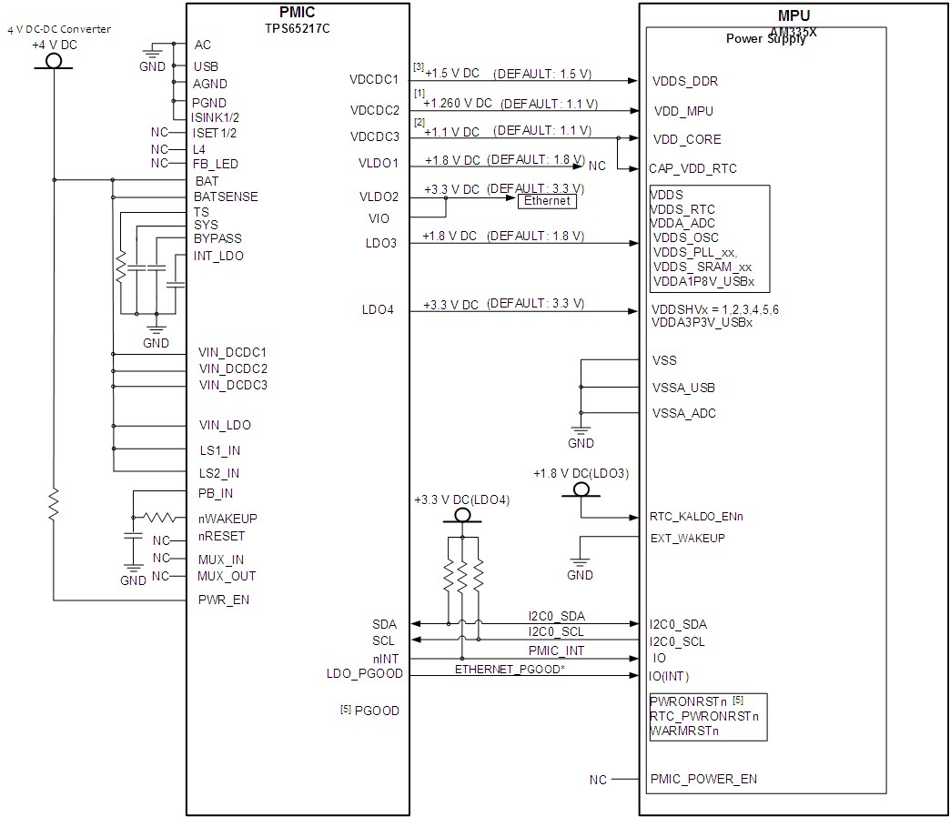
    Please ignore my follow up query asked on Aug 20, 2016 2:54 PM. Please consider this post as valid as we have changed some connection in figure after having further clarity. Please refer AM335X checklist for "RTC timer functionality but no RTC-only mode" for VDDS_RTC, PMIC_POWER_EN, CAP_VDD_RTC and EXT_WAKEUP  connection for AM335X.

    We are using only VBAT (DC supply, Its  not battery supply) and not using AC and USB supply. We want out device to be turned on as soon as it receive VBAT supply(4V to 6V). We have left Reset unconnected and PWR_EN is pulled high.

    Please find my answer embedded below in blue  in response to your suggestions.

    Richard : Why not still use LDO1? Even though Strobe 15 does not start without a wakeup event, it will still occur before LDO3. Since you don't appear to be using the PMIC_POWER_EN, this should be OK, but the notes in the AM335x datasheet mention that ramping VDDS_RTC after the core will cause additional leakage on the core rail.

    Manoj : As we understand from user guide of TPS65217X, referring TPS65217C power up sequence, that LDO3(VDDS_RTC, VDDS supply) will also powered up 6ms before VDCDC3(VDDCORE supply) so there will not be any leakage current as per AM335X schematic checklist for "RTC timer functionality but no RTC-only mode". Please refer note 4 on page 6 in RTC section.

    We are also supplying CAP_VDD_RTC from VDCDC3 (VDDCORE supply) as per Am335X checklist for "RTC timer functionality but no RTC-only mode"so CAP_VDD_RTC will also come up along with VDDCORE supply  so there will not be any leakage current as per AM335X datsheet, figure 6-5 note F.

    Richard : I would not recommend omitting nWakeup or nReset, as I don't know how this will affect the PMIC driver and could limit your design in the future.

    Manoj : Please refer TPS65217C user guide for connections (figure5), nRESET is left unconnected. We dont have any case where we need to reset PMIC once it is started.In TI BB schematic it is shown NC.

    For wakeup signal connection: we have connected this(wake up) signal to PB_IN, PB_IN is having one capacitor to ground to provide low pulse during power up and then after 50ms wakeup signal will go low to provide low pulse on PB_IN. since PWR_EN pin is pulled up so PMIC device will enter active mode, wake up will go high after 50ms sensing PWR_EN pin high which will also ensure high on PB_IN.

    Below is our working mode as per state diagram.

    On Power up PMIC will be in off state : A low pulse on PB_IN will send PMIC in WAIT PWR_EN state, as PWR_EN is pulled up high wake up will be high in 50ms and device will enter in active mode, this will also ensure that PB_IN will not be low for more than 8 sec hence avoiding the reset state. .In case of fault device will enter in off state  until fault is removed. Wake up signal will go low in fault condition which will pulled PB_IN pin low so sonce fault condition is removed device will reenter in active state as explained above. Pleas confirm. I am also attaching my PMIC connections figure below , please provide your feed back as per above explanation verifying connection diagram..


  • Hi Manoj,

    For a valid wakeup event, your capacitor would have to be large enough to hold PB_IN below 0.4V for the deglitch time of ~50ms.
    Until this wakeup event has been recognized, nWAKEUP will not be pulled low.
  • Hi Richard,

    Thanks for your response. Please Provide confirmation on the entire scheme considering that the capacitor we have selected will provide 100 ms deglitch time.
  • Hi Manoj,


    With regards to the connections to the processor, I don't see why they wouldn't work.

    For the PMIC, assuming your capacitor will maintain PB_in <0.4V for >50ms, this configuration work. However, this assumes ideal conditions on every start, so I would recommend thorough fault testing during your validation phase to ensure it responds as expected when power-cycling etc.