This thread has been locked.

If you have a related question, please click the "Ask a related question" button in the top right corner. The newly created question will be automatically linked to this question.

TPS65381-Q1: Question about BIST timing and Overcurrent protection function

Guru 19485 points
Part Number: TPS65381-Q1
Other Parts Discussed in Thread: TPS653850-Q1,

Please let me know about three points below for TPS65381-Q1 (and TPS653850-Q1).

①I think that BIST function begin after VDD6 rail ramps, is it correct?

 If any other condition for BIST begin, please let me know.

 (Isn't BIST function from the beginning? )

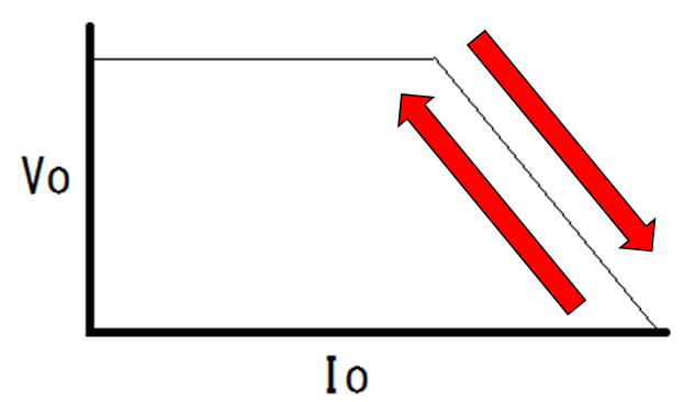
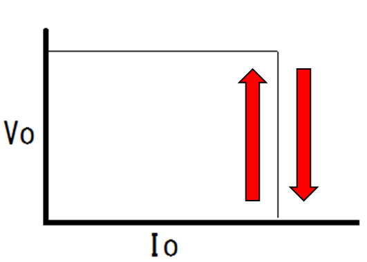
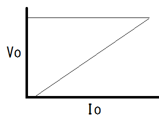
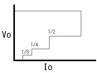
②Which is the TPS65381-Q1's overcurrent protection below? 

  No,1           No.2    No.3      No.4

③About the above question ① and ②, is TPS653850-Q1 the same function (answer)?

Best regards,

Satoshi

  • Hi Satoshi-san,

    A1: Please refer to Figure 5-1 in Revision F datasheet of the device. The Device State shows when BISTS run automatically at power up of the device. ABIST runs automatically at device power up (from STANDBY) when VDD6 powers up. The device continues through it's power up sequence and once the rails have fully ramped and the RESET extension time has expired you will see the device transitions from RESET state to DIAGNOSTIC state. Full BIST (LBIST, which also re-runs ABIST) runs at this time. BIST will also be run automatically any time the device transitions from RESET state to DIAGNOSIC state unless AUTO_BIST_DIS bit in the SAFETY_BIST_CTRL register is set. Setting this bit will NOT disable the BIST run at power up from STANDBY. This is further explained in section 5.4.1.6 Logic Built-In Self-Test (LBIST) section of the datasheet.

    A2: I'm checking with the team on how to best answer the current limit question. I will get back to you later this week.

    A3: The TPS653850-Q1 device is a device covered by non-disclosure agreement and cannot be supported in the public E2E Forum. Please send me a private message with your e-mail contact, or contact your TI FAE or sales support so I can find the appropriate channels to support it for you.

    Thanks and Best Regards,
    Scott
  • Scott-san

    Thank you for reply.
    I understood BIST function and TPS653850-Q1.
    I looking forward to update overcurrent function.

    Best regards,
    Satoshi
  • Hi Satoshi-san,

    For Q2 the answer (A2) is dependent on which regulator in the device:

    VDD6 buck pre-regulator:  the current limit is base on the peak current through the internal FET switch so the way it limits current will not translate to the above sort of "average" current limit graphs but will depend on many factors, but the internal switch current will limit based on peak current. 

    VDD5 and VDD3/5 regulators: limit the current like No 3, they will "overshoot" during a short then snap back to a lower current as this graphic shows.

    VDD1 (LDO controller with external FET):  no current limit directly in the control loop, the assumed configuration is VDD1 is supplied from VDD6 and the VDD6 current limit will then limit VDD1 current.

    VSOUT1 (sensor supply):  Is sort of between graphic No 1 and No 2.

    Best Regards,

    Scott

  • Scott-san

    Thank you for reply,
    And sorry for addition about BIST function (Question-1).

    During BIST run, please let me know what operation for Fault detect and Protection.
    ※For example;
      Until BIST run complete, continue the abnormal condition and outputting Fault output signal.
      ⇒After BIST run complete, protection is start.

    If this thinking is wrong, please let me know about correct operation.

    Best regards,
    Satoshi
  • Hi Satoshi-san,

    I believe your understanding is almost correct.  This BIST functionality is described in sections 5.4.1.5 and 5.4.1.6 of the datasheet.  As noted in Section 5.4.1.5:

    "During an active ABIST run, the device cannot monitor the state of the regulated supplies, and the ENDRV pin is pulled low. The full ABIST run time is approximately 300 μs."'

    Thus during ABIST (and equivalent for LBIST) as an example, the regulation from a VDDx regulator is not impacted, but it is also not monitored during the BIST time.  So if it failed exactly during the ABIST run, the OV or UV would not be detected until BIST was completed, then the flag would set or the device action for the fault would occur per the state diagram for the specific fault.  As a precaution during the BIST runs, ENDRV, the safing output pin, is not allowed to be high so the safing path to the outputs should be "off" and thus even if there is a fault at that time, it cannot propagate to the system outputs.

    Best Regards,

    Scott 

  • Since there has been no follow up since Feb 28, 2017 I'm assuming this topic is closed so I will close the thread here on E2E. If you have futher questions please start a new thread. Scott