Other Parts Discussed in Thread: AM3505, TPS650250
Dear E2E Support,
My cutomer has some start-up issue with our TPS65023 which power our AM3505.
Here is his description below:
On scope 5 :
- Yellow trace => +5V_ALIM (Main Power supply of the PMIC)
- red Trace => +1.8V (Power supply of DDR and a part of the CPU)
- Green Trace => +3.3V (Power supply of main 3.3V)
- Blue trace => VDDSHV_EN (Enable command of +3.3V PMIC Output)
Scope5

I do not understand what happened on +1.8V.
The start up is OK and 1.8V is reach for 2ms and it continue to rise until 2.7V. The slope seems the same as +5V_ALIM and +3.3V_ALIM.
Do you know this problem and how to solve it?
We have some products where the +1.8V stays always to 2.7V supply and the board is KO (it’s not possible to launch application…)
When we withdraw the CPU, after start up, Power supply 1.8V is OK. It doesn’t rise until 2.7V.
First remark : When I put a 100nF capacitor on VDDSHV_EN (or for C70 ), power startup is OK (see scope 4). But we must be carefull because the +1.2V(for the core supply) and 1.8V_USB/3.3V_USB LDOs will start before the 3.3V (is it a pb?)
Scope4:

Second remark : 3.3V – 2.7V = 0.6V it seems to be a voltage clamp diode ! What is the electronic interface between the +1.8V domain (VDDS/VDDS_SRAM/VDDS_DPLL/VDDSOSC) and +3.3V domain (VDDSHV) of the CPU?
Other scope if it can help to understand the power supply sequence:
Scope_8
Yellow: +5V_ALIM
Green: +3.3V
Pink: +1.8V
Bleue: +1.2V

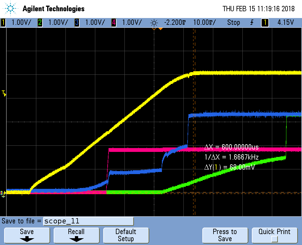
And scope_9:
Yellow: +5V_ALIM
Green: +3.3V_USB
Pink: +1.8V
Bleue: +1.8V_USB

I can share the schematic in private message if needed.
Regards,