This thread has been locked.

If you have a related question, please click the "Ask a related question" button in the top right corner. The newly created question will be automatically linked to this question.

TPS65070EVM-430: Software does nothing

Part Number: TPS65070EVM-430
Other Parts Discussed in Thread: TPS65070, USB2ANY, IPG-UI, TPS65023, TPS65217,

Hi TI,

I'm starting to work with the TPS65070. With the EVM came a USB Interface Adapter. First time plugging in, the firmware has been updated and the software also tells me in the lower left corner that  the "USB Bridge is Operational.". However, I can't do anything with the TPS65070. The light on the adpater is on and there is 5V on the AC pins.

When I press the read button next to the registers, nothing happens. If I change anything, press write, give it about half a minute and press read, it changes back to all zeros. Also the default values as given in the datasheet don't come up. It stays all zero.

I handled the EVM board with care, it just came out of the sacket (on which an other part number was printed, but the right one is on the board) and I've used ESD mat and bracelet.

Is it broken or do I do something wrong?

  • Hello and thank you for posting this question on the e2e forum.

    I have a TPS65070 EVM in the lab and the TPS6507x GUI software installed on my PC, so I can test this in the lab to try to identify the issue you are having.

    I will report back with my results as soon as possible, but it may take 24-48 hrs to respond.
  • After testing with a new TPS65070EM-430 and a new "USB Interface Adapter" (HPA172), I have confirmed that the EVM and GUI software are working and compatible.

    My concern with your setup would be that the AC and GND pins on header J2 are very close to each other.

    Is it possible that AC and GND were shorted together accidentally? I usually apply AC at J2 and connect GND at J3 when I am testing this EVM (and the opposite for USB: connect USB at J3, GND at J2 to test USB input).

    Another concern would be that maybe the POWER_ON jumper was removed. Please verify that the POWER_ON jumper at JP6 is connected to the HIGH position.

    Here are some screen shots of the working GUI:

    In the first screen shot, I read the Registers in PPath1/INT tab. For the INT register, I see that USB/AC voltage Applied = 1b on the first read and resets to 0b on the second read.

    In the second screenshot I navigated to the WLED_CTRL1/2 tab at the end to make sure I could turn on the LEDs then modify the brightness with the PWM slider. This was also successful on my EVM.

  • The pins have a normal distance. I worked with female-female to make sure there would be no short circuit when the cables are loose. I only attach the males when I connect the cable.

    The power, JP6 is connected at the high position.
    The user interface looks the same, but I can click whatever I want and it just stays all zeros, even after writing something to it and reading it again.

    edit: I tried figuring out what the problem is. With a logic analyzer on the I2C pins I got a strange readings. Attached is a measurement of 10sec in which i write right after each other to 0x01h: 00111111, 00111110, 00111100, 00111000, 00110000, 00100000, 00000000. All done with the TI GUI for TPS6507x. The measurements show no real clock and no real data send. All 'messages' consist of the clock and data going low, both going high again for a short while and then low again. Attached are also screenshots of the first two 'messages' zoomed in and as a whole.

    I think something is really wrong.

    tps65070.zip

  • I am familiar with Saleae scope, so I have an additional request:

    • Can you re-capture the scope image using the "Analog" channels on the scope? You just click on the button to the right of "Start Simulation" in the Saleae Logic software GUI. The button looks like up & down arrows. You just enable the channels 0-7 with the "sine wave" graphic next to them. Screen shot below
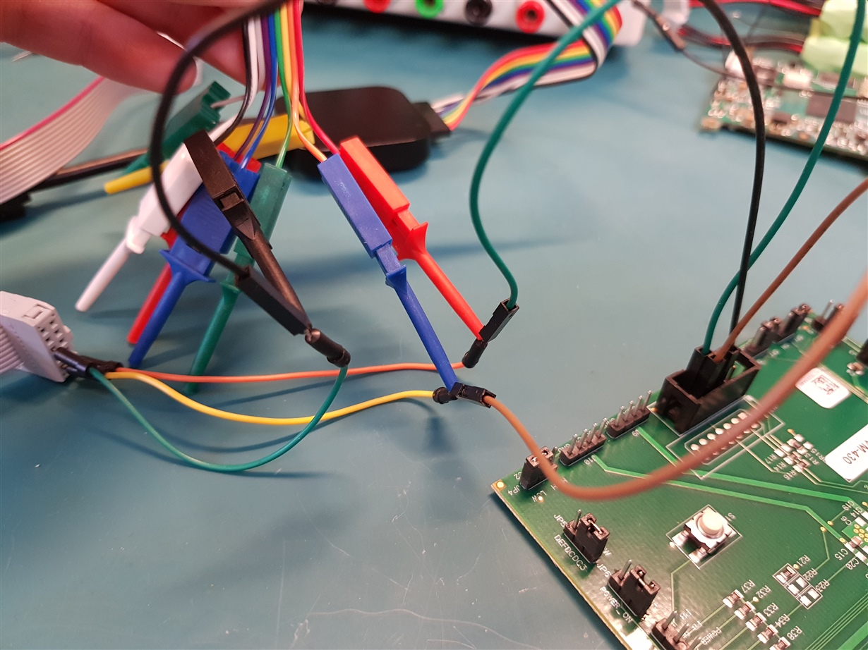
    • Can you also take a picture of your setup with a phone? It is the only way to verify the connections.

    It does look like something is wrong with the I2C data but it is tough to say what is wrong because you are only capturing the digital values of the SCL & SDA lines. When you use "Analog" measurements, you can also add other channels (AC voltage, USB voltage, PWR_EN signal, etc.) as long as they do not exceed that Abs Max of the Saleae scope (I think it is 10V, but please double check by reading Saleae spec sheet).

    Thanks,

    Brian

  • Screen shot of Saleae software showing how to enable "Analog channels" below (I do not have scope connected to PC):

  • This version of the saleae is only a logic analyzer. It cannot measure analog signals.

    With a scope I made some images sending 00000011 to 0x01h. The scope images are made with the connector attached directly. The logic images with cables, so I could attach the hooks.

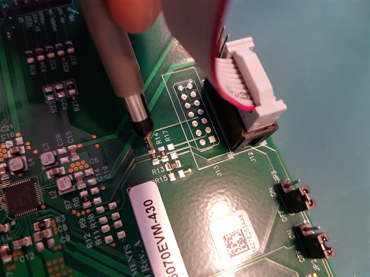
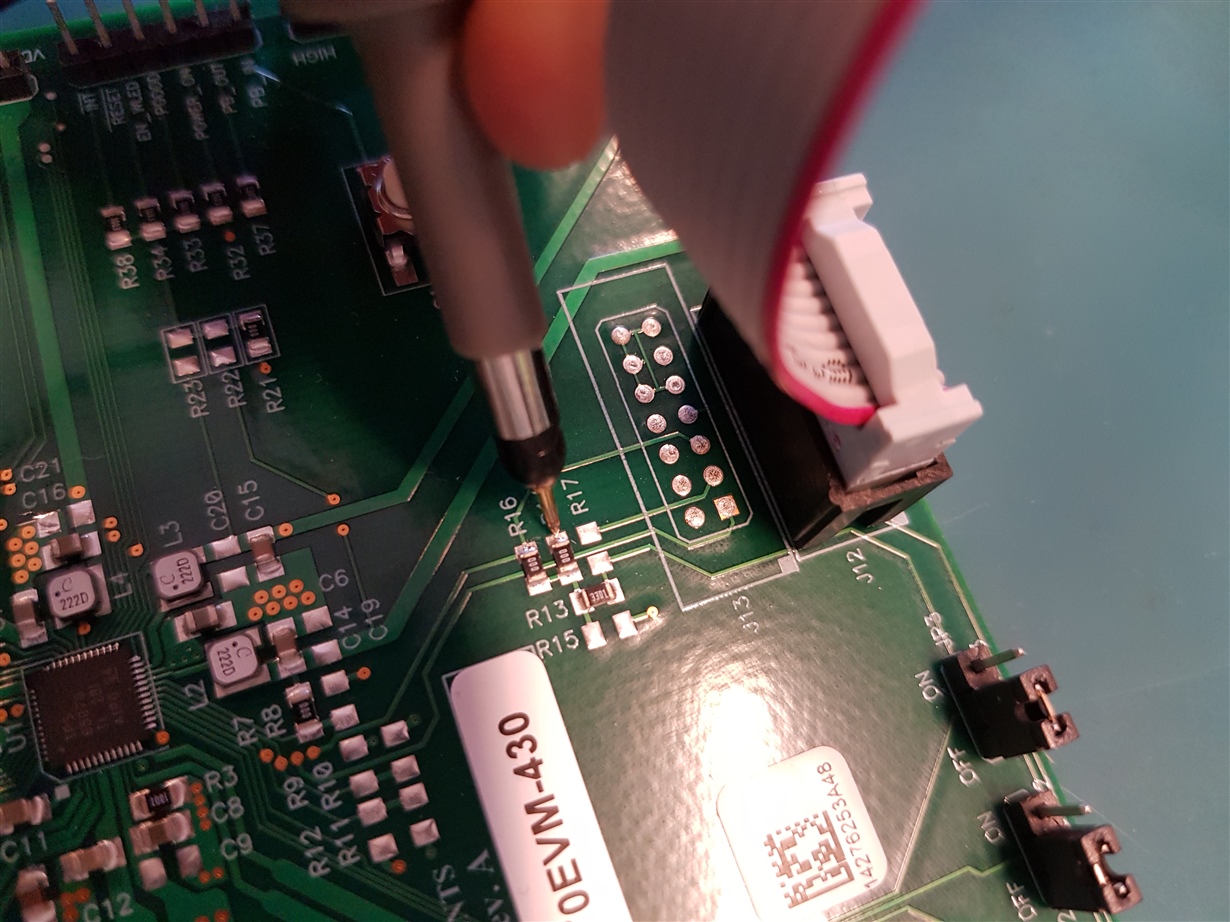
    Scope images are measured on R14 and R16. It is only this negative pulse here. Zoomed out there is nothing else to find. Images are taken seperatly but look identical...

    R14

    R16

  • For now, all I can say is that I agree that the I2C lines appear to get stuck low during data transmission. It is possible the adapter was "bricked" during the Firmware (FW) update the first time you launched the GUI. It's not 100% bricked, but maybe the FW was corrupted enough to make this "stuck low only during transmission" behavior occur.

    Do you have any other "Adapter Box" from TI?

    This one is labeled HPA172 and can be found on the Web (www.ti.com/.../USB-TO-GPIO) but we also have an adapter called USB2ANY (www.ti.com/.../USB2ANY) that ships with most of our new devices. For example, the TPS65023 and TPS65217 are shipping with the USB2ANY and use PMIC-specific GUI named IPG-UI (http://www.ti.com/tool/IPG-UI). The IPG-UI does not support TPS65070 directly, but it has a generic I2C template that can be used to Read/Write raw data.

    Non-TI I2C adapters include the TotalPhase Aardvark (www.totalphase.com/.../).


    If you do not have another adapter to try, we will have to explore options for providing you a new USB-to-I2C adapter to test. If you provide your e-mail address on e2e or contact a TI Sales Rep, we can figure out how to provide a new adapter.
  • Hi, sorry for the late reply.

    I don't have an other Adapter box from TI. Who and how should I make contact? I rather don't place my e-mailadres in the open.

    Thanks in advance,

    Karolijn

  • Karolijn,

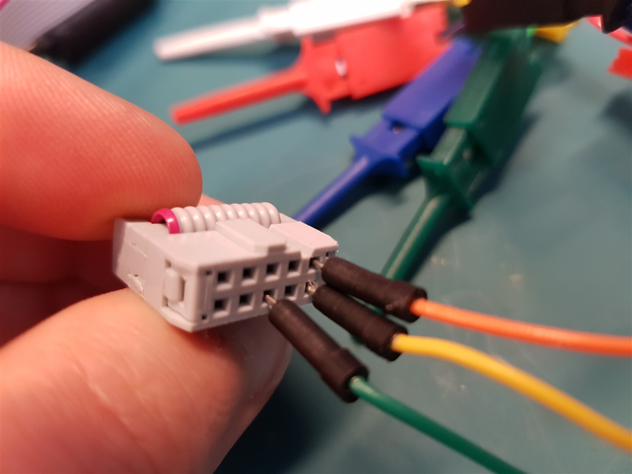
    Although I think it is unlikely to be the root cause of the problem, one of the photos you sent worried me: it looks like the I2C "blue wires" from the Saleae to the TPS65070EVM-430 board are not connected to the right pins.

    On the Saleae side, it looks correct. Although I cannot see the ">" arrow pointing to pin 1 on the ribbon cable connector, the red wire is on the correct side. You are either connected to pins 6, 9 ,and 10 (correct) or pins 5, 9, and 10 (this would be bad).

    On the TPS65070EVM-430 side though, it looks quite clear that pins 3, 7, and 8 are connected.

    I counted from the pin 1 marking on the silkscreen next to the female header.

    From the EVM schematic, all pins except 6, 9, and 10 are floating:

    This may invalidate the Saleae captures but does not explain the analog scope captures unless there is another wiring issue. I see the scope probe is measuring the correct side of R14 for SDA, but SDA could be all 0s. If you probe R16 for the clock (SCL), it will be a better indicator.

  • Hi,

    There is also a scope image or R16, looks the same as R14. And all wires were connected correctly, although indeed not really clear from the picture I took.
    But the problem is found.
    Yesterday I could borrow an Aardvark from somebody and that also didn't work. There is quite a large mistake on the EVM board. Resistors R14 and R16 were 0R. So connected to each other and not able to do anything of course.
    There are replaced with 3k3 and now the board seems to work.
  • Thank you for confirming the root cause for the issue.

    This is a large assembly mistake, so I will reach out to the team at the distribution center and ask them to verify the assembly of all R14/R16 values for the remaining EVMs in stock.

    Hopefully we can prevent this issue from occurring again in the future thanks to your help.