This thread has been locked.

If you have a related question, please click the "Ask a related question" button in the top right corner. The newly created question will be automatically linked to this question.

TPS65910: PMIC not functioning with AM3358

Part Number: TPS65910
Other Parts Discussed in Thread: AM3358, USB2ANY, TMDSSK3358, TMP112

Team,

Please see below customer question:

We are using the AM3358 (Z1) with the TPS65910A31A1 PMIC spec’d in. Our CM substituted TPS65910A3A1 parts.The datasheet doesn’t state the differences. Can you describe if they can be substitutes?

Also, we are experiencing a series of failures where the AM3358 seems to lock up and a PMIC reset (long power button press) doesn’t reset the micro.

I have looked at two of our assembled units which are exhibiting this problem. In both the PMIC is producing VDD_MPU = 1.1, VDD_CORE = 1.1, VDDS_DDR = 0. 

If we completely remove power the PMIC will be reset and the units will reboot.

This problem state is spurious and difficult to repeat. Getting the same unit to repeat the failure mode hasn’t worked reliably.

Please ask your factory if they have ever encountered this problem and if the substitute PMIC could be the problem. If it isn’t the problem, see if they have any ideas. We are scheduled to launch the product next week, but this could be a show stopper.
  • Team,
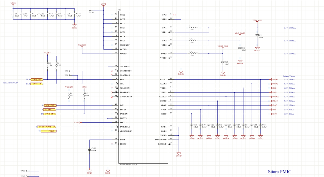
    I asked the customer to verify if VRTC_REG.VRTC_OFFMASK has been modified from 0 to 1 and look into pins 10, 11 and 33.
    These pins are slightly modified from the recommendation on TPS65910Ax User Guide for AM335x Processors
    www.ti.com/.../swcu093f.pdf
  • Hi Randhir,

    The difference between the two is the VRTC regulator mode in the OFF state. The A3A1 has the VRTC in low-power mode in OFF to minimze quiescent current, but it cannot support more than 100 uA of current in this mode. If current draw is higher than this in OFF state, the VRTC will crash (or fail to reach 1.8V) and the part won't function properly since VRTC powers the internal digital.

    In the ON state, the two should be the same.

    I have not seen VDDS_DDR issues before. I have seen cases where there were too many pull-downs on the VRTC rail and so the A3A1 was failing where the A31A1 would successfully boot, but this sounds like it is not a boot problem.

    Not connecting pins 10 and 11 will result in voltage scaling not working unless the SR_CTL_I2C_SEL bit is changed to 1b.

    For the long power button press, what does the INT signal do? A long key press should shut the PMIC down unless the processor is clearing the INT (datasheet pg 49).
  • A follow up: are you able to hack into the I2C lines to talk to the PMIC with an external controller, like USB2ANY? I'm curious if the VDDS__DDR rail is possibly being disabled or set to 0V accidentaly by the processor. We could read the registers and see what writes the PMIC has received.
  • Thanks Kevin. I have shared your feedback with the customer and will update you with their results
  • Kevin/Brian,

    See below feedback form the customer:
    I2c transactions that we perform in normal operation of the device. Please let me know if anything feels suspicious or incorrect.
    1. Linux bootup (some i2c init traffic generated by kernel while booting up)
    2. Power button detection (We write and clear the PWRON_IT bit in INT_STS_REG register to detect our custom power off timing)
    3. Clear the INT_STS_REG before executing the poweroff command in Linux (write value 0xff)
    4. Linux pm_poweroff hook uses ALARM in pmic to poweroff in usual TI Linux kernel way.
    Other that this we have other devices on i2c bus and we do read and write to them for different purposes. I don’t think that might have something to do with the VDDS_DDR issue.
    We added the INT1 mod on a unit that was having this issue. Our observation was the INT1 signal was high initially, when we pressed the power button for 7 sec the INT1 signal went low and after we released the power button the signal was high again. It seems that the processor is not clearing the interrupt that is being generated

    +

    Customer based their design on TMDSSK3358 for the original layout with the TPS 65910A3 as the PMIC. It did not use the Smartreflex pins. See page 5 if the attached reference schematic.  I confirmed that thy were not needed with Rebel. Ultimately to properly implement the low power modes, we moved to the A31A1 version around January 2016. The design when using the A31A1 part has been working fine since then.


    We are going to attempt to hack the board (while it is still powered) to see if we can control the i2c bus. If we disconnect the power the problem state is gone and no longer observable.

  • Hi Randhir,

    Thank you for the follow up. Seeing that the INT1 is toggling and the PMIC is responding to the address command, but not the register command, would suggest the PMIC core at least is still running.

    1. Do we know yet when the system is locking up? Is it on boot or is it after running for a while for example.

    2. On a locked up system, is the VRTC voltage stable at 1.8V? If it is either not reaching 1.8V or dropping below 1.8V then we would expect issues.

    3. For the long button press, if you press for > 8s, does the PMIC shutdown like normal? 

    4. Can we get scope shots of the I2C commands for Case 1: Beaglebone hacked into the locked board? We could try to analyze if the I2C appears irregular in any way. 

    My first thought is maybe the VRTC load is spiking above max current for the A3A1 part version (100 uA) during the boot before the device in the ACTIVE state and that maybe this is corrupting the OFF2ACT transition? That guess would at least explain why this issue wasn't observed for the A31A1 systems. 

  • Could it be going in sleep mode and PMIC regs SLEEP_KEEP_RES_ON and SLEEP_KEEP_LDO_ON are set so that only SWIO is affected?

  • Aaron above is part of the team working on this issue for my customer. 

    I have sent an internal email passing along the customer's response since it contained some file attachments of some scopeshots. 

    Thanks,

    Brian

  • We looked at PMIC register dump from working unit.  The sleep registers look OK but we can't be sure of the values after the lock up.

    Attached is the register dump.

    The only thing we noticed

    i2cdump_success.txt
         0  1  2  3  4  5  6  7  8  9  a  b  c  d  e  f    0123456789abcdef
    00: 00 00 00 00 00 00 00 00 00 00 00 00 00 00 00 00    ................
    10: 00 00 00 00 00 00 00 00 00 00 00 00 9f 0d 01 00    ............???.
    20: 01 0d 3d 00 05 2e 00 04 00 00 00 00 00 00 00 00    ??=.?..?........
    30: 09 0d 01 0d 0d 0d 09 01 0d 00 00 00 00 00 3b 70    ?????????.....;p
    40: 35 00 00 00 00 00 00 00 00 00 00 00 00 00 00 00    5...............
    50: 10 02 00 00 00 00 00 00 00 00 00 00 00 00 00 00    ??..............
    60: 0a 0a 0a 0a 0a 0a 00 00 00 00 00 00 00 00 00 00    ??????..........
    70: 00 00 00 00 00 00 00 00 00 00 00 00 00 00 00 00    ................
    80: 01 00 00 00 00 00 00 00 00 00 00 00 00 00 00 00    ?...............
    90: 00 00 00 00 00 00 00 00 00 00 00 00 00 00 00 00    ................
    a0: 00 00 00 00 00 00 00 00 00 00 00 00 00 00 00 00    ................
    b0: 00 00 00 00 00 00 00 00 00 00 00 00 00 00 00 00    ................
    c0: 00 00 00 00 00 00 00 00 00 00 00 00 00 00 00 00    ................
    d0: 00 00 00 00 00 00 00 00 00 00 00 00 00 00 00 00    ................
    e0: 00 00 00 00 00 00 00 00 00 00 00 00 00 00 00 00    ................
    f0: 00 00 00 00 00 00 00 00 00 00 00 00 00 00 00 00    ................
    
    
    is ILMAX is 0 on VIO_REG, VDD1_REG and VDD2_REG, so we need to correct those.  For example schematic shows SWIO 1000mA but we have PMIC set at maximum load current of 500mA.

  • Hi Aaron / Brian,

    Thank you for checking with the TPS65910A31 and confirming the issue can still be reproduced, that means no need to focus on VRTC.

    Let me know the results of the ILMAX test. If drawing 1A with minimum ILMAX, then the part could detect a short circuit and shut the rail down until rebooted which sounds consistent with the identified failure.

    An alternate test for the same goal would be to try to disconnect VIO from the load and power the load externally and see if the failure still occurs. 

  • They tested setting ILMAX to 01 (1.0A) in VIO_REG, that did not fix the issue but a workaround was found to prevent it.

    The PMIC register dump shows some register values that look like writes intended for another device on the I2C bus. Some code changes were made to prevent multiple threads from trying to access the bus simultaneously. They have not seen the issue in any testing since making that change.

    These are the devices on that bus.
    0x2d: PMIC
    0x36: Fuelgauge
    0x69: Battery Charger
    0x48: TMP112 temperature sensor
  • Thank you for the follow up Aaron, good to know the issue is resolved.