This thread has been locked.

If you have a related question, please click the "Ask a related question" button in the top right corner. The newly created question will be automatically linked to this question.

TPS65381A-Q1: TPS always is Safety and Standby State

Part Number: TPS65381A-Q1
Other Parts Discussed in Thread: TMS470MF06607,

Hi

I am working on TPS65381A-Q1 device and controller used is TMS470MF06607.

I am trying to read the TPS device state which is always showing that it is in Safe State and sometimes in Standby State.

I am trying to read error status too. 'WDG_FAIL' and 'ERR_PIN_FAIL'  bits are getting set.

I tried being in the diagnostic state by setting 'DIAG_EXIT_MASK'  bit and disabling 'DIAG_EXIT' bit but still the current device state is either Safe mode or  Standby.

Even I tried reading back the 'DIAG_EXIT_MASK' and 'DIAG_EXIT' bit and showed both are set to '1'.

Please help me find out issue at the earliest so that I may enter 'Diagnostic State' and 'Active State'  and carry out further task.

Regards

Mayank Bhatt

  • Hi Mayank,

    I've assigned this to our relevant expert.
  • Hi Mayank,

    Please make sure if your are debugging with the TPS65381A-Q1 and you want to stay in DIAGNOSTIC state that the DIAG_EXIT_MASK bit is set within 512ms (typical) of the TPS65381A-Q1 releasing the reset pin, NRES, high.  There is DIAGNOSTIC state time-out on the device, if you wait longer than 512ms after the NRES pin goes high, the device has will transition to SAFE state due to the DIAGNOSTIC state time-out.

    My guess is that your are not configuring the TPS device in the DIAGNOSTIC time before this timeout occurs. Also, if there are enough faults incrementing the DEV_ERR_CNT[3:0] >= PWD_THR [3:0] the device will transition to off state.  

    Hopefully you can debug and get the device configuration and necessary system diagnostics done or the DIAG_EXIT_MASK bit set prior to the DIAGNOSTIC state time-out.

    Best Regards,

    Scott

  • Hi Scott

    Thanks for your response.

    As I am not enabling 'WDG_RST_EN" so I also assume that 'WDG_FAIL' and 'ERR_PIN_FAIL'  bits are getting set because of Diagnostic timeout but issue is that first statement after SPI initialization in 'main' is  setting "DIAG_EXIT_MASK".

    I don't think startup code and initialization takes more than 512 ms but still I am clueless.

    In another project we are using TMS570 controller and we are able to get into Diagnostic state following exactly similar procedure as TMS470.

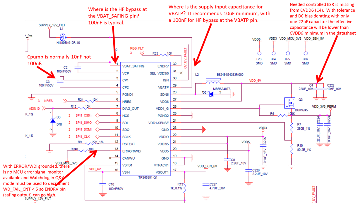
    I am attaching snip of schematic of  TPS device, please have a look and help me resolve it ASAP.

    Regards

    Mayank Bhatt 

  • Hi Scott

    Thanks for your response.

    As I am not enabling 'WDG_RST_EN" so I also assume that 'WDG_FAIL' and 'ERR_PIN_FAIL' bits are getting set because of Diagnostic timeout but issue is that first statement after SPI initialization in 'main' is setting "DIAG_EXIT_MASK".

    I don't think startup code and initialization takes more than 512 ms but still I am clueless.

    In another project we are using TMS570 controller and we are able to get into Diagnostic state following exactly similar procedure as TMS470.

    I am attaching snip of schematic of TPS device, please have a look and help me resolve it ASAP.

    Regards

    Mayank Bhatt
  • Hi Mayank,

    WD_RST_EN has no impact on DIAGNOSTIC state time-out.  This bit only controls if the TPS65381A-Q1 will go through RESET state (resetting the MCU via NRES pin) when the WD_FAIL_CNT reaches 7 + 1.  

    Both the WD_FAIL and ERROR_PIN_FAIL flags will be set if DIAGNSOTIC state time-out occurs, even if DIAG_EXIT_MASK bit is successfully used (with DIAG_EXIT bit cleared) prior to DIAGNOSTIC state time-out.  If you then run DIAGNOSTICs and try to then go to ACTIVE state by setting DIAG_EXIT and clearing DIAG_EXIT_MASK (in one write) so the SAFETY_CHECK_CTRL register the device will go to SAFE state since these FAIL flags are set.  This is seen in Figure 5-16. Device Controller State Diagram.  You should use a scope or logic analyzer to verify the timing of the NRES release (high) to the SPI commands to the TPS that they are in time and the correct SPI commands to configure and keep or put the TPS65381A-Q1 into the state you want at the correct timing.   Also, check your TMS470 code is really doing something similar as TMS570.  

    So you may have a couple of software paths why the device is in SAFE, either DIAGNOSTIC state time-out or not clearing the WD_FAIL and ERROR_PIN_FAIL flags before transitioning to ACTIVE state.  There could be other detected issues in your system causing the transition to SAFE, please look on this diagram and SAFE state sections to make sure you haven't done one of the other faults causing this transition.

    I have looked at your schematics and there isn't anything schematically that will directly lead to SAFE state, but there are a couple of indirect possibilities.  ERROR/WDI is grounded so there is no possibility to use the MCU Error Signal Monitor (ESM).  If the MCU ESM is enable in your software, the ERROR_PIN_FAIL will always occur since the ERROR/WDI is grounded.  Also, to use ENDRV pin to go high, you will have to use the watchdog in Q&A mode.  ENDRV pin can only be enabled to go high after W_FAIL_CNT is decremented < 5.

    There are other issues I've found and outlined in the schematics below.  Those may be causing high ripple or poor regulation of the device.  

    Hopefully this will help you find your issue.  

    Best Regards,

    Scott

  • Thanks Scott

    I was trying exactly similar procedure earlier as suggested by you but when I changed linker script of the project and relocated vector back to 0x0 address (which was earlier different) I was able to change state to diagnostic state as well as active state but only when I am in debug mode and doing step in.
    I am unable to understand why it worked when linker script is changed.

    Please help me understand it.

    I feel there is some timing issue which is causing the same because if I put breakpoint then I couldn't see my states as per my requirement.

    I would be grateful if you help me till TPS works as per my requirement.


    Best Regards
    Mayank Bhatt
  • Hi Mayank,

    Linker/compiler topics are for the MCU team.  I support only the TPS65381A-Q1.  This PMIC will always run independently in real time.  As mentioned before once the wake up event triggers a power up of this device it will run on its timing. So once the NRES pin goes high all internal timers to the TPS65381A-Q1 are running and DIAGNOSTIC state time-out will occur if the necessary steps are not taken by the MCU.

    I cannot say what changing the linker did to the software flow, but obviously it caused issues that the MCU was not providing the necessary SPI frames to the TPS65381A-Q1 in time.  Using a scope with SPI debug capability or a small logic analyzer tool to monitor time from NRES going high to when the SPI frames are sent to the TPS65381A-Q1 is a valuable tool to confirm your software running as expected and is communicating with the TPS65381A-Q1 as it requires for the real time it is monitoring from the MCU and other system inputs.

    I would recommend posting to the MCU forum about the linker script and debugger impact.  In general using a debugger with the real time monitoring devices such as TPS65381A-Q1 is a challenge.  As a trade-off of this challenge is the DIAG_EXIT_MASK bit to allow a short boot code to start the TPS65381A-Q1 and get it into DIAGNOSTIC state and hold it there until the debugger (non-real time) and any other non-real time software debug tools can be started without impact to the TPS65381A-Q1.

    Best Regards,

    Scott

  • Scott

    Surely I will post in MCU topics.

    If TPS enters SAFE state because of diagnostic timeout, is it like I have to do a Power On Reset and then have to process MCU commands to get the device in diagnostic state?

    Because many times TPS enters safe state and I have to power off and on again and thenit enters diagnostic state when I set "DIAG_EXIT_MASK" bit.

    As per my schematic my board (MCU) gets power from TPS and IGN has to be always ON to make MCU ON. Will it pose some issue?

    I am not using wake up via CAN.

    Please understand as the project state is critical so I have to continue getting help from your side. 

    Regards

    Mayank

  • Hi Mayank,

    Once the TPS65381A-Q1 goes into its SAFE state there are multiple options to transition the device back to DIAGNOSTIC.  These are shown in the section 5.4.19 Device Operating States, Figure 5-16. Device Controller State Diagram.   One option is to lower the IGN pin to transition back to STANDBY state then re-wake up the TPS65381A-Q1 by raising IGN again powering up through RESET to DIAGNSTIC state.  Another option is to force a state transition to RESET state to then get back to DIAGNOSTIC state.  One of these is to use the SAFE state time-out options (assuming you can configure them before getting to SAFE state) or force a watchdog failure while WD_RST_EN = 1.  If this is just for software debug purposes another method could be to externally force CANWU high (even though it is not used in the normal application), then send the WR_CAN_STBY command.  Technically this causes a partial transition to STANDBY state for 1 device clock cycle which is too fast to transition there, because CANWU is high the device will immediately "re-start" and go to RESET state then DIAGNOSTIC state.

    For device wake up (power up) you have to use either IGN pin (assumed to be ignition / KL15) or CANWU pin (assumed to be INH output from CAN transceiver).

    If your MCU has to remain powered and I assume not have a reset (NRES low) for debug purposes you may have to disconnect the NRES pin to RESET pin of the MCU during this debug process to prevent the transition through RESET state from resetting the MCU.

    Normally most customers put a small bootloader into the MCU to power it up and get to and stay in DIAGNOSTIC state using the DIAG_EXIT_MASK command.  After the MCU and TPS boot to this state they then connect the debugger and do software development.  This avoids trying to use a debugger which is non-real time to get to the DIAGNOSTIC state.   

    Scott


  • Hello Scott

    Thanks for your input.

    I tried toggling a GPIO pin in free running mode (not debug mode) whenever my state changes to "Diagnostic State" and "Diagnostic to Active" and I could observe state changes.
    I kept a small delay ( 100 times 'for loop' iterations) after each CS high to next CS low.

    But another issue popped up.

    I was trying to enable VSOUT1 whose voltage output I could see 1.5V by default, it should be 0V as per datasheet.
    Also I tried disabling VDD5 which is always ON by default. I could get proper 5V as VDD5 output.
    I couldnot enable or disable these despite of giving proper SPI commands.

    Please help for the same.


    Best Regards
    Mayank Bhatt
  • Hi Mayank,

    VSOUT1 is disabled by default (VSOUT1_EN = 0, default).  You have to set VSOUT1_EN bit to 1 to enable it.  If you are measuring voltage on VSOUT1 without enabling it, you have a leakage path in your circuit to VSOUT1 through some other device.  VDD5 is enabled by default (VDD5_EN = 1, default), but can be disabled by clearing VDD5_EN to 0. 

    Both of these bits are in the SENS_CTRL register. There is no write lock by the device in any state on these so a proper SPI write to the register should enable or disable these regulators based on the VSOUT1_EN and VDD5_EN bit status.  Did you use the SW_LOCK command to lock registers against writes? 

    Best Regards,

    Scott

  • Scott

    I followed similar procedure and it worked after so many attempts without a change in the code.

    Regards

    Mayank Bhatt