This thread has been locked.

If you have a related question, please click the "Ask a related question" button in the top right corner. The newly created question will be automatically linked to this question.

TPS2561 auto retry timing

Other Parts Discussed in Thread: TPS2561, TPS2553

 Regarding the TI TPS2561, which has active low OC pins and active high enables; if my hub controller doesn't have output pins to drive the enables, can I connect them to the over current lines, and let the power switch disable itself in an OC situation?

  • Yes, you can do this for an "auto-retry" function. Please see figure 19 on page 16 of the datasheet.

  • I have been trying to implement the auto-retry function but I can only seem to get retry periods of ~12ms using the circuit shown regardless of the RC time constant used. I would like the retry period to be longer (~1 second). Is this possible without external components.
  • Can you send your schematic?
  • It is the same schematic as on the datasheet.  Adjusting the Rext and Cretry does not seem to give expected retry time based on RC time constant.


  • I discussed briefly with design and we agree that FAULT should go low (~10ms after an OCP fault) briefly until the de-asserted EN pin removes gate drive from the FAULT output FET. Then the R-C should set some delay for the EN pin to rise from near zero up to the EN threshold of ~0.8V.

    I did not have a TPS2561 EVM to test this on but found an EVM with the same FAULT design (TPS2553). I will look on the bench on Monday and gather wave forms. In the meantime, if you gathered wave forms, please send them.

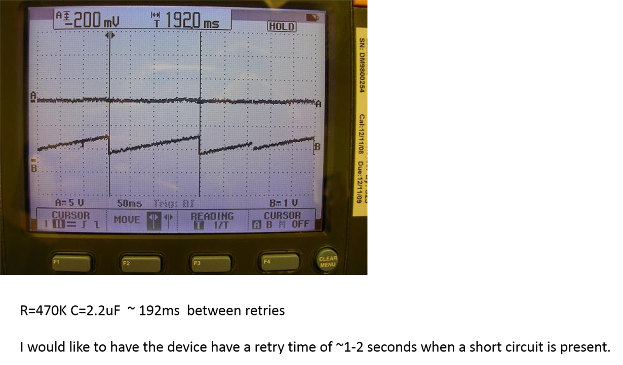
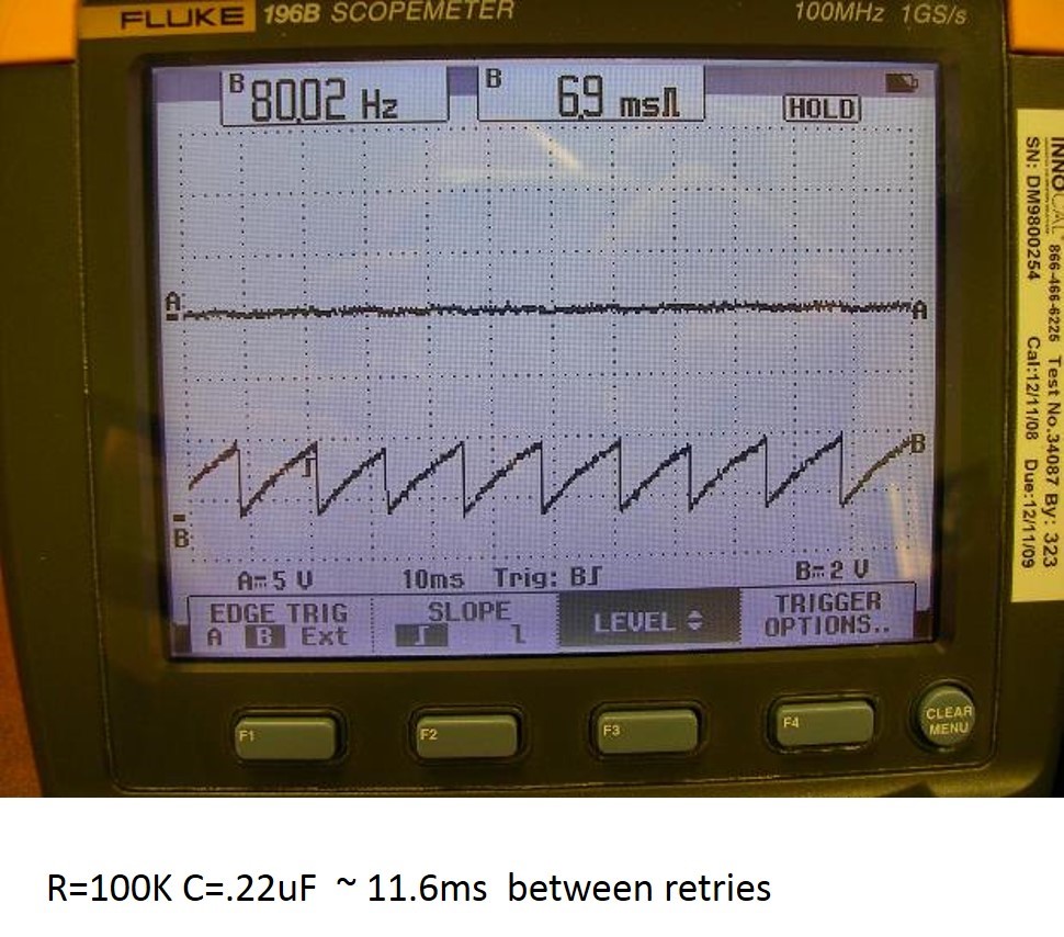
  • See the attached ppt file with scope shots of output voltage (chA) and Fault'/enable during short circuit conditions. I'd like to have the device operate more in "hiccup" mode with about 1-2s retry time. Thanks.

  • Thanks for the wave forms. From these, I can see some effect on the FAULTx pin saturation voltage due to the size of the capacitor (larger capacitors take a higher current to discharge and the saturation voltage will be higher at the valley point of the wave form. For the 0.22uF capacitor, the saturation voltage is quite close to zero and for the 2.2uF capacitors the saturation voltage is ~0.3V - 0.4V. There is also an effect due to the FAULTx pin deglitch timer (9ms nominal) which will allow the capacitor to charge beyond the EN pin threshold of 0.8V (typical). This deglitch effect is more pronounced with shorter retry times.

    In theory, the time between retries is -R x C x LN (1-Ven/(Vin-Vflt)) + Tfault where Ven is the EN pin threshold, Vin is the input voltage, Vflt is the FAULTx pin saturation voltage, and Tfault is the internal FAULT deglitch time. This seems to be inline with the times you've measured.

    It may be difficult to get a predictable retry time in the 1 second range due to the saturation and EN and FLT pin leakage effects. Making the capacitor larger will yield higher FAULT pin saturation voltages and making the resistor too large may induce some leakage effects (from both EN and FAULTx pin). Generally, these leakages can be ignored but with a large resistor the EN settling voltage should be measured over temperature.

    That being said, if you keep the 2.2uF capacitor and increase the resistor to 2.5Meg then you should have a retry time in the 1 second range.

  • Eric,

    Thanks.  This makes sense and matches what I found.  I used a 2.2uF and 4.7Mohm and got ~2 second retry time i wanted.  The On time for the Output voltage (time from saturation voltage to trigger (~0.8V) is < 0.4s so it pretty much approximates a standard hiccup control.  I will check over temp to ensure the 4.7Meg doesn't cause leakage current issues.  thanks for your input.  Below is channel A the output voltage and channel B is the fault/enable pin.  

    Thanks again.