This thread has been locked.

If you have a related question, please click the "Ask a related question" button in the top right corner. The newly created question will be automatically linked to this question.

LM5050 draw current

Other Parts Discussed in Thread: LM5050MK-1EVAL

Hi

Our customer evaluate LM5050 with LM5050MK-1EVAL.

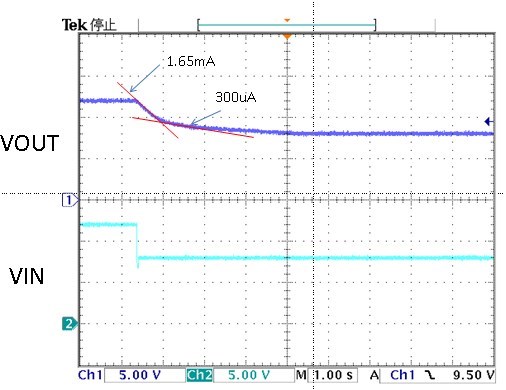
Then they got the phenomenon below.


Where is the current draw from.

(The power supply is not current draw type.)

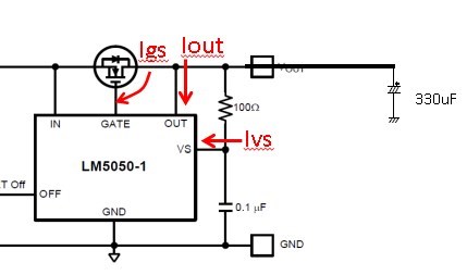
Are the current draw Ivs+Iout+Igs.

Also how much the draw current are they if so.

Regards,


  • Hamamoto-san,

    What is the operating condition you are testing at? Please describe what you are doing to get that waveform? From the schematic above are you saying you're open circuiting the input and the output cap is discharging through OUT and VS pins and the customer wants to know how much the current is under that condition?

    Regards,

    Darwin 

  • Hi Darwin-san

    Thank you for your reply.

    Condition is, 

      Vout waveform is observed when Vin is changed to 8V from 12V.

       This waveform means there are some draw current from Cout. 

       This draw current path is our question. Does VS pin sink some current?

       No load. (There is only a capacitor which is 300uF) 

    Please let me know If you have any questions.

    Regards,


  • Hi Darwin-san

    Please let me add my comment for your questions.

    >What is the operating condition you are testing at?

      - Please see above conditions. 

          Vin=8V to 12V, No load , Cout=330uF

          It is only a variation of VIN voltage.

    >Please describe what you are doing to get that waveform?

          I changed the VIN voltage from 8V to 12V transiently.

    >From the schematic above are you saying you're open circuiting the input and the output cap is discharging through OUT and VS pins and the customer wants to know how much the current is under that condition?

         Please see below the circuit which I was evaluated.


     I think the draw current are the sum of Ivs and Iout and Igs.  Is that correct.

      How much current are assumed at each pins if so.

      ( I did not find the sink current specification for each pins.)


    Regards,


  • Hamamoto-san,

    All input current measurements for IIN, IOUT, IVS in the typical performance characteristics graphs on the datasheet are for VIN=VS=VOUT. Unfortunately there are no current measurements taken for different VIN and VOUT and VS values so it may be that the input currents increase under these condition. I recommend verifying this by biasing the output and VS to 12V with a power supply while biasing the input at 8V with another power supply and measuring the individual currents. This will show how the LM5050 currents behave under different biasing conditions.

  • Hi Darwin-san

    Thank you for your reply.

    I was relieved unlikely to be a problem with this phenomenon at least.I will try to measure in a way that you had described.

    Thank you.

    Regards,

  • Hi Darwin-san

    > I recommend verifying this by biasing the output and VS to 12V with a power supply while biasing the input at 8V with another power supply and measuring the individual currents.

    I measured these current as you provided to me how to measure.

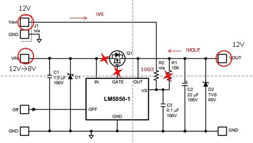
    The test circuit is below. VIN,Vext(VS),VOUT are biased by individual power supply.

    The results are,

      1. VIN=12V,VOUT=12V,Vext(VS)=12V @Ta= room temp

          -> IVOUT=0.004mA , IVS=0.116mA

      2. VIN=8V,VOUT=12V,Vext(VS)=12V

          -> IVOUT=1.58mA, IVS=0.11mA

    IVOUT increased when VIN is 8V. (Also IVOUT increase IVOUT=1.73 when Ta=70degC)

    Q1: Could you explain these mechanism of draw current.(why the draw current is increased. )

    Q2: Is it possible how to estimate these maximum current.

       (The reason for the customer will use in battery applications this circuit.)

    Please let me know if you have any questions.

    Regards,