This thread has been locked.

If you have a related question, please click the "Ask a related question" button in the top right corner. The newly created question will be automatically linked to this question.

TPS23754 inverse local power

Other Parts Discussed in Thread: TPS23753

I have a special application, where I want to provide local power, e.g. via option 1, for cases when there is no PoE power available. Conversely, if there is PoE power available, we would like to transfer part of that power over the same local power pair to a remote location, i.e. reverse power flow. Has any body done this?

  • HI Michael,

    Do you have block diagram of what your applicaiton is doing? So the local power rail sources (when no PoE) and sinks (with PoE)?

  • Hi Darwin,

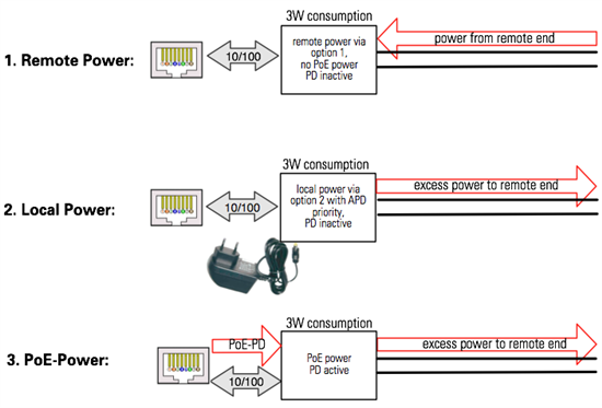
    yes, here is a block diagram. There are 3 operation cases, depending on the power source. I am having no problem sinking the power. But how would I source power to the remote end in the last 2 cases?

    Case 1 is straight forward, using power option 1 from the report. A bridge rectifier ensures correct polarity.

    Case 2 is also clear from the power source, using an adapter with option 2; adapter preference using the APD pin function.

    Case 2 and case 3 should also deliver power to the remote end, i.e. sourcing, and "going around" the bridge rectifier used for case 1.

    Any ideas are appreciated, Michael

  • Hi Michael,

    Option 1 would not be an appropriate option for this application seeing as the remote power line can also sink current. When the PoE power is connected, the remote load will prevent the PoE side from detecting and classifying. The remote power/load would have to be after the PD such as on option 2.  

    Will the remote end 'know' when PoE or adapter is inputted and 'know' to switch from sourcing to sinking current? Then you can simply directly connect the remote end after the PD. 

    This is not an application I've seen before.

  • Hi Darwin,

    understood. We would need a circuit, which would signal the presence of PoE power or adapter power and only then connect the remote line via a MOSFET, for example.

    No, the remote end does not know anything about the local end. It will see the remote input as adapter power, when not supplied otherwise. Both units, local and remote, are identical.

  • I have a question regarding the PoE Present block in Figure 4 on page 6 of SLAV306A: Is it correct to state that PoE present detection is only possible in connection with Option 2 and Option 3 ORing solutions? Is there any way to detect active PoE operation in the presence of adapter power via Option 1 ORing? How would I get a signal to detect PoE present with 48VDC adapter priority?
  • Hi Michael,

    Please see the summary table on page 4 of SLVA306C. You are limited in flexibility when you are designing option 1 with PoE priority. When the adapter is present first, PoE cannot detect and classify so thus cannot startup.

  • Hi,

    yes, I did study this table. My preference would be Option 2 with adapter priority. From the table I take APD Y 1,5V which is the case and VDD connected to VDD1, i.e. no diode DVDD.

    But in this case the PoE Present block from Figure 4 would not work, or would it?

  • Hi Michael,

    Option 2, adapter priority does not require the PoE present block. Section 3.3 and figure 8 describe the operation of that circuit.

  • Hi,

    you are right, but I need the PoE Present signaling for another function. Is there a way to signal PoE active with Option 2 and adapter priority?

  • You could use the Qp/Dp (+2x 10k resistors) circuit of figure 5 or the Up/Dp circuit of figure 6. When the POE source is ON then Qp or Up opto transistor would be ON. Once the option 2 adapter (with enough voltage to put the APD pin above 1.5V) is connected, then the TPS23753 internal FET will turn off and interrupt current flow from the POE source. The POE source should detect that current stopped flowing and then turn OFF. This will then turn off either the Qp or Up opto transistors signalling POE not present.

    Once the adapter is disconnected, the POE source (assuming it is still connected) should re-acquire and re-power the circuit turning Qp or Up back on.

  • Yes, that was my thinking too, however it does not work: My guess is that the adapter power feeds back from VDD1 to VDD (no diode because of adapter priority) and the body diode of the internal hot swap. As a result Qp or Up are ON for PoE AND adapter power. Or do you think I am doing something wrong?

  • Michael, you are right about the voltage getting fed back to VDD/VSS when there is no Dvdd between VDD and VDD1. In order for the Qp or Up circuit to accurately signal POE present, Dvdd should be used so that the voltage between VDD and VSS can collapse and turn off the Qp or Up circuit (when the adapter is present).

    Sorry I missed that. Without Dvdd, the body diode of the internal FET provides a conduction path for the adapter voltage and this keeps VSS at a diode drop above the RTN pin when the adapter is present. Adding Dvdd interrupts this current path.

  • OK, but then with the diode Dvdd in place I am getting a conflict and it seems that the PoE is not really disconnected. I still see Qp/Up staying ON when adapter power is provided.

    - Dvdd diode for PoE priority

    - APD for adapter priority

    Who wins in this case? 

  • Is the POE source turning off and removing the VDD-VSS bias for the Qp circuit? Are you using a real POE PSE source or just a power supply? A true PSE should disconnect when the port current goes below 5mA and then the Qp circuit should turn off. With Dvdd in place, the voltage would collapse and the PSE would then be able to detect, classify, and power up again. But the current should be below 5mA and the PSE would again turn off. This cycle should repeat with the Qp circuit cycling as well. Is that what you are observing?

    If you really wanted to keep the PSE from successfully detecting again (after powering off the first time) then you would have to corrupt the detection signature using a circuit similar to figure 10 (using the DEN pin to turn off the internal FET instead of APD). This circuit could detect when the adapter was present (input of opto) and then corrupt the 25k detection resistor so that once the PSE powered OFF it would not be able to successfully detect again (with follow on power up) until the adapter was removed.

  • Thanks, I will try that and get back.

  • Understood now - thank you. Regarding figures 3, Option 2 with PoE preference, is it harmful to use an 48V adapter with just the diode Da? I want to avoid the extra circuitry of figures 5 or 6, but have an 48V adapter.

    I want to understand, why there is a restriction of using on lower-voltage adapters with figure 3. I don't see any problem with the PSE dropping power due to dc MPS when adapter voltage is higher than PSE voltage.

  • For example, (using figure 3):

    • Adapter ispresent and the adapter voltage is 48.0V. The voltage between VDD1 and RTN will be a diode drop below 48.0V.
    • Now, a PSE is connected to the RJ45 connector and successfully detects and classifies followed by power up. Assume that the PSE ON voltage is also 48.0V. Now, the PSE ON voltage between VDD and VSS will be ~2 diode drops below 48.0V (due to the diode bridge rectifier).
    • For this case, Dvdd would be reverse biased by a diode drop and current would not flow from the PSE. After some time (~350ms)  the PSE would remove power and power would continue to flow from the adapter.

    So, while you could use a higher voltage adapter you would need to ensure that current flows from the PSE so that it keeps the port powered.

  • I have 3 different power sources: PoE, Adapter via option 1, and adapter via option 2. Regardless of priorities, is there a way to tell that the TPS23753 is being powered by PoE? I need a signal like "PSE supply active". Any ideas?

  • I am concerned with regard to figure 6 of slva306a.pdf:

    Doesn't the body diode of the MOSFET Ma effectively ground the negative input of the plug power supply and render the disconnect circuit useless?