This thread has been locked.

If you have a related question, please click the "Ask a related question" button in the top right corner. The newly created question will be automatically linked to this question.

LM5072 RAUX input down to 9V ???

Other Parts Discussed in Thread: LM5072, LP2951

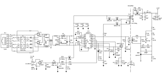
We have a circuit built using the LM5072 that uses the RAUX input for external power to our device.  The circuit doesn't output anything (doesn't appear to turn on) until about 14.2 volts on the input.   This seems to agree with the data sheet that describes the regulator turn-on voltage of 14.5 volts. 

SO HOW is thing spec'd to operate down to 9V input?   My circuit will continue to operate down to 9VDC, but only after it's been turned on with a voltage above 14.5V.  There must be something I'm missing.

I need to be able to put 9V into this thing and have it produce 12V out, and start up properly.   What do I need to look at, change, etc.??

Thanks

Jerry/NJ

  • Hi Jerry,

    Is the 9V powering the between VCC and RTN? Also, is the RAUX voltage higher than the rising threshold of 3V? Can you send a schematic of your PD design? Thanks!

  • No, 9V is on the Vin input, referenced to GND (RTN).  I'll try to send this portion of schematic.  RAUX voltage is 9V or higher.

  • Hi Jerry,

    What is the voltage on VCC? It must be 8-15V. Notice on page 19 of the datasheet regarding low input voltages. You will need supply the VCC directly from the Aux voltage via diode ORing.

    Regards,

    Darwin

  • OK Darwin, I got the circuit to start up by using the diode-or.   So I can use the Raux input down to 9V or so.   BUT then I went to test the high side by cranking the RAUX input up to 30+ volts, and I blew the diode that was being used to connect the aux input to Vcc.   Is the diode or'ing supposed to work at all voltages?

    The diode I used was only a 200mA forward current diode.   I could use a higher-current version, but is this advisable?  How much current is drawn on Vcc typically?

  • Hi Jerry,

    The abs max rating on the VCC pin is 16V, since it is ORing with the bias winding, the 30W is being seen at this pin. Typically, the adapter voltage is a set voltage (ex 12V wall wart) where it won't exceed the abs max rating.

    At higher adapter voltages, if you need to switch to the bias winding voltage, you will need some kind of logic switch to not allow the high adapter voltage get to VCC.

    Or you can add an LDO with a wide input range to power the VCC pin from the adapter. The current is only 3mA max at 10V. 

  • I like the LDO idea.  My problem is that I want to keep this running at 9V adapter input.  With voltage drops due to necessary parts required on the input, I've had issues with getting the circuit to startup.

    What is the Vcc threshold I need to be above (the LDO regulator voltage, in this case) to guarantee the circuit will start up?

  • For normal operation the design should be between 8-15V with UVLO being a little less than 8V. Since your minimum input voltage is 9V and using an LDO means you have to choose a lower output voltage, I would recommend you use 8.5V or so.

    This is a bit tricky because you have to consider the dropout of the LDO. But since the current is so low, you might get a away a little higher voltage than 8.5V without going into dropout.

  • Hi Jerry,

    I wanted to check with you to see if you were able to start up fine at higher aux voltages using the LDO?

    Also, we are interested in your design and this solution and wanted to talk to you about your application? Can we email you directly offline? If so, can you forward me your email? My email is shown below:

    dfernandez@ti.com

    Thanks!

  • Hey Darwin,

    Thanks for checking in!  YES, I was able to get the circuit working completely.  I needed to eliminate the diode bridge on the input because we are getting too much voltage drop across it.  So we will go with dedicated + and - inputs for DC, with some other protection method.   

    To simulate the LDO without needing to build up an actual circuit, I just used a bench power supply to input a fixed voltage to Vcc through a diode.  I'm setting the supply to 8.5 volts or so.  Works in all conditions.  We're going to spec our DC input as 12 to 24 VDC - it will work down to 9 to accommodate droop or voltage drop, and up to 27+ to accommodate a 24V supply that's 10% high.

    The LDO I plan on using is a Linear Tech LT3011 (sorry), unless TI has a similar one that's cheaper.  Its output will be set to 8.56V, and thus the voltage on Vcc will be about 8V after a diode drop.

    Let me know what info you'd like to have, and I certainly appreciate the help.

    Thanks,

    Jerry

  • I've changed the LDO to the Texas Instr LP2951.  It's almost a tenth of the price of the Linear Tech part.