This thread has been locked.

If you have a related question, please click the "Ask a related question" button in the top right corner. The newly created question will be automatically linked to this question.

To check TPS23753 schematics

Other Parts Discussed in Thread: TPS23753, TLV431A, TLV431, TPS23753A


 Hello

One of my customer is evaluating TPS23753 as gateway. He would like to get 12V output from TPS23753.

He designed the schematics base on TPS23753AEVM-005, However VDD is less than 8V.

Even he changed  component to TPS23753AEVM-005 from TPS23753AEVM-003, but VDD is same as his board.

If R22(EVM) or R737(Customer Board) changed to 5.1K, VDD is around 12V, but Power supply current is increasing(It is no load condition)

Please reveiw customer schematics and if you have any idea about this issue, let me konw.


Changing component for EVM

C21 : 47nF -> 15nF

R28 : 348R -> 301R

R22 : 422R ->  2.49K(VDD 7.85V with 3.5mA) & 5.1K (VDD 11.88V with 17.2mA) in no load condition.

R21 : 2K -> 15K

C19 : 10nF -> 6.8nF

U3 : TLV431A -> TL431B (adjust pin map)

R24 : 24.3K -> 3.24K

R19 : 41.2K -> 12.4K

Q1 : IRF8113 -> IRF7855

C12, C13 : 47uF/6.3V -> 10uF/16V

C14 : 330uF/6.3V -> 68uF/25V

T2 : HA3801-AL -> HA3803-BL


Customer Schematics

Gateway_PoE Board_Rev0 1_20141114 (2).pdf


  • Hi Jacob,

    When you say VDD, do you mean VOUT?

    We will look into the schematic and get back to you.
  • We too encountered the same issue replicating TPS23753EVM-004 Schematic and BOM in our design.

    Reference design suggested R22 = 1k, but we have to use 2k-ohm for PoE to work.

    When setting R22= 1k, we noticed VC < 7V, VB < 5V, which indicated TPS23753 was not in normal operating state,
    however, 125KHz switching signal was observed with ~20% duty cycle.
  • Also we noticed TLV431 may not in the proper working state even when R22 was set to 2k,
    where Cathode was measured 1.6V, and VREF measured 0.8V.
  • Did you try converting the -004 EVM to the -005 EVM by following the BOM column for X=-005? We have made this conversion many times and the boards have always worked fine. If you had trouble with the actual EVM board conversion then we should take a look at the board and troubleshoot it.,

    If your board is not working, then it might be good to compare side-by-side with a working EVM converted to the -005 for troubleshooting purposes.

  • Eric Wright said:

    Did you try converting the -004 EVM to the -005 EVM by following the BOM column for X=-005? We have made this conversion many times and the boards have always worked fine. If you had trouble with the actual EVM board conversion then we should take a look at the board and troubleshoot it.,

    If your board is not working, then it might be good to compare side-by-side with a working EVM converted to the -005 for troubleshooting purposes.

    The component value we used are almost full replica of EVM X=004, except

    1) Q1 IRF8113  ->  SI4848DY

    2) D12 BAV99 -> BAT54S

    3) C14 330uF Al Cap -> 22uF X5R Cap

    The PoE Vout refuse to get to the designed 5V until we changed R22 from suggested 1k to 2k.

    We have now tens of PoE samples working now.

    I think there's something to play with the CTR of photo-coupler TCMT1700, in the R22 = 1k configuration, the volt on CTL pin of TPS23753 input is way below 1.8V that placed the converter into 0% duty cycle state, suggesting a higher than expect CTR.

  • I think there's something to play with the CTR of photo-coupler TCMT1700"

     Please confirm the part # for the opto-The TPS23753AEVM-005 BOM for U2 shows a different part #:

    U2 TCMT1107 IC, Photocoupler, 3750VRMS, 80-160% CTR MF4 TCMT1107 Vishay

     Also ensure that U3 was changed to the 36V regulator as shown:

    U3 TL431ACDBVR IC, Shunt Regulator, 2.49-V ref, 36-V, 10-mA, 1% SOT23-5 TL431ACDBVR TI

    R22=2.49k for EVM -005(12V), 1k for EVM-003(5) and 422 for EVM-004(3.3V). See Table 4 of SLVU314E.

    For a 12V output the 2k seems reasonable and will bias the opto closer to 5mA.

  • Sorry there are numerous typo in my former post, to correct that
    (1) we were using TCMT1107 not TCMT1700, and the CTR ranking is 80~160%.
    (2) we were using EVM-003 (5Vout) BOM, and first set R22 to 1k (not working), then changed to 2k.
  • Just to confirm, are you using the TI EVM PCB modified for 5V out or your own PCB? By changing R22 to 2k, you lower the loop gain. It is possible that the circuit was unstable (maybe due to some other factor) and by reducing the gain, you were able to operate semi-normally. With R22=1k, what does the voltage on the TPS23753A CTL pin look like? If you see oscillation, that can be a sign of loop instability. Under normal DC operation the CTL pin voltage should remain stable around ~2V depending on output loading.

  • Eric Wright said:

    Just to confirm, are you using the TI EVM PCB modified for 5V out or your own PCB? By changing R22 to 2k, you lower the loop gain. It is possible that the circuit was unstable (maybe due to some other factor) and by reducing the gain, you were able to operate semi-normally. With R22=1k, what does the voltage on the TPS23753A CTL pin look like? If you see oscillation, that can be a sign of loop instability. Under normal DC operation the CTL pin voltage should remain stable around ~2V depending on output loading.

    We have very limited board size, both sides of 4L boards were used for placement, and some of the feedback circuits are placed in close proximity to main transformer, but none of them were placed right underneath the transformer.

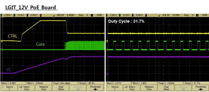
    Below figure shows R22=1k configuration, the Vc droops right after mofset's switching, and Vout is away from designed value.

    Zoom-in version

    CTL signal are noisy in 100mV scale, mainly due to switching noise (bad probe ref gnd selection), no severe oscillation was observed.

    Below figure shows R22=2.2k configuration, the Vc boosted to over 10V, suggesting a successful start up, and Vout can go beyond 5V.

    Increased R22 pushes the duty cycle to > 30%.

    Zoom-in version

  • It is odd that Vout will not regulate at 5.0V (you said that Vout is at 5.8V) when R19=41.2k and R24=13.3k (even with R22=2k). Did you also change T2 on your boards to the HA3802-BL (5V flyback transformer)? From the plots, it seems that the turns ratio for the 5V output is not correct and that is why I'm asking,

    The "fuzz" on CTL doesn't seem too bad (no wild oscillations > 1V pk-pk). Design of the feedback loop does take into account the ESR of the output filters. You've replaced a 330uF (C14)  electrolytic capacitor with 2x 22uF ceramics and that may have an effect on stability under certain conditions (although I cannot see any artifacts in the waveforms you've shown).

  • Hello Eric

    It seems like that Lenny had same problem about converting EVM.

    I attached customer waveform and it didn't look like instable.


    I will try to convert step by step however I am warry about the customer schedule.

    If you don't mind, I would like to send converting EVM. Please check what is problem with it.

    Could you let me know your address to send the board?


    Thank you

  • If you can get the board to your local TI sales office then they can get it to me in Dallas, TX.
  • Eric.Today, I got them, I will send to you.Please inform your detail address.
  • Hi Eric,

    Trying to convert TPS23753AEVM for 12V output, we faced the same problem,
    Did you have any solution ?

    Best regards
    Stathis
  • Hi Stathis,

    Do you have a schematic of your design that we can review? The 12V BOM solution has been used many times. There could be an incorrect component value or connection somewhere on the board. Thanks!
  • Darwin Fernandez said:
    Hi Stathis,

    Do you have a schematic of your design that we can review? The 12V BOM solution has been used many times. There could be an incorrect component value or connection somewhere on the board. Thanks!

    Hi Darwin,

    Thank you for your reply,

    I spent 3 days in vain,  trying to find a solution, attached please find the schematic.

    Regards

    StathisPoE_Project.pdfhis

  • Hi Stathis,

    I notice the synch FET is 30V. For the 12V solution this should be the 60V FET. It could be that the synch FET is damaged.
  • Hi Darwin,

    Thank you, we will replace the FET and I will inform you.
  • You were right everything is OK now thank you