This thread has been locked.

If you have a related question, please click the "Ask a related question" button in the top right corner. The newly created question will be automatically linked to this question.

TPS23753 output fluctating

Other Parts Discussed in Thread: TPS23753, TPS23753AEVM-004, TPS23753A

Hi, 

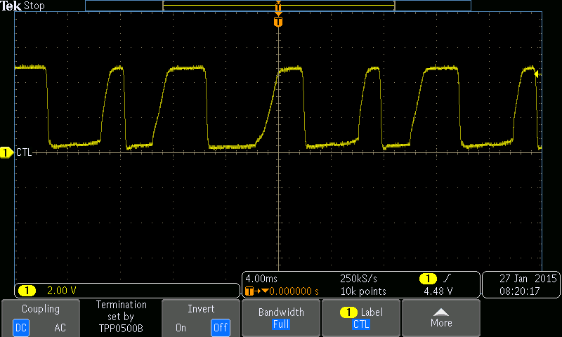
We are using TPS23753 IC as PoE controller IC and generating 5V output. It is generating 5V output but sometimes its output is not constant. It is fluctating. I have attached the snapshot of output. We also probed its switching frequency when we got this issue, its switching frequency is also not proper. There is so much variation in it. Snapshot for that is also attached. I have also attached the schematic for this design.

When we are getting smooth output, then there is no fluctation in output and switching frequency. 

Please help us to resolve this issue.PoE.zip

  • The FOD2742B has an internal 2.5V reference and should be biased higher to ensure the rated CTR (140% at Iled=10mA). Try reducing the value of R159 to increase the bias. 261 ohm will get the bias closer to 5mA as a start.
  • Hi Eric,

    Thanks for your reply. We tried by reducing this resistor value to 261 ohm but still we are getting the same issue.

    I also tried by changing the capacitor C186  value 2.2uf to 22uF, with this change this issue is coming very low. But issue is not fully resolved yet.

    Please let us know next action item on this.

  • Can you provide the voltage waveform at the TPS23753 VC pin?
  • Hi Eric, 

    We probed at VC pin of TPS23753. When we are getting this issue voltage waveform at VC is not constant, it is fluctating. But when we are not getting this PoE issue, voltage waveform at VC pin is constant. I have attached both these waveforms taken at VC pin.Without PoE issue at VC pin.zip

  • For the mis-behaving case, Vc appears to droop below ~5.5V which re-cycles the converter. The appearance is that of an unstable loop but according to the schematic provided, I cannot see any issue. Here are a couple of basic questions:

    1. Is this a brand new design or one that was working and now is not?

    2. Do you have more than one PCBA behaving the same way or just one?

    3. Have you verified that all of the installed components including capacitors match the schematic? It can be difficult to measure the smaller value loop compensation capacitors without having an LCR meter.

    4. Have you tried powering the converter w/o the POE by connecting the supply between VDD and RTN nodes? You can also start out at lower voltages (maybe 24V and above) to see if the circuit behaves better and then slowly ramp up while monitoring the node voltages.

    5. Do you have access to a network analyzer to use for measuring the loop stability? If there is a stability issue, then that can help you tune it for the Fairchild opto+error amp. As I mentioned before, we normally use a 1.5V error amp and compensate for that. This helps with compensation.

    6. What does the CTL pin look like when the circuit is misbehaving? Does it oscillate too (similar to the Vc profile)? This is also a sign of an unstable loop.

  • Eric Wright said:

    For the mis-behaving case, Vc appears to droop below ~5.5V which re-cycles the converter. The appearance is that of an unstable loop but according to the schematic provided, I cannot see any issue. Here are a couple of basic questions:

    1. Is this a brand new design or one that was working and now is not?

    2. Do you have more than one PCBA behaving the same way or just one?

    3. Have you verified that all of the installed components including capacitors match the schematic? It can be difficult to measure the smaller value loop compensation capacitors without having an LCR meter.

    4. Have you tried powering the converter w/o the POE by connecting the supply between VDD and RTN nodes? You can also start out at lower voltages (maybe 24V and above) to see if the circuit behaves better and then slowly ramp up while monitoring the node voltages.

    5. Do you have access to a network analyzer to use for measuring the loop stability? If there is a stability issue, then that can help you tune it for the Fairchild opto+error amp. As I mentioned before, we normally use a 1.5V error amp and compensate for that. This helps with compensation.

    6. What does the CTL pin look like when the circuit is misbehaving? Does it oscillate too (similar to the Vc profile)? This is also a sign of an unstable loop.

    Hi Eric, 

    Thanks for your reply. please find my answers inline:

    1. Earlier this design was working fine. We just did re-layout in next revision and now we are facing this issue.

    2. We are facing this issue on multiple PCBs. We made 100 PCB, we are facing issue this issue almost 60 PCBs.

    3. Yes, we have verified all components. These are OK.

    4. Yes, we tried by directly giving 48V without PoE. With this also this issue is coming.

    5.We don't have access to network analyser to measure loop stability.

    6. CTL pin is also oscillating when circuit is misbehaving. I have also attached the waveform taken at CTL pin.

  • Please examine the layout difference between the previous working design and this PCB design especially with respect to routing of the CTL pin trace (pin 1 of TPS23753A). If the CTL trace is routed too closely to noisy switching signals then the loop stability will be affected. We have the following text in the TPS23753AEVM-004 user guide, but we should make it clearer about the sensitivity of the CTL pin trace/signal.

  • Hi Eric,

    Thanks for your reply. We checked the layout difference between two revisions of board. There is no layout difference for TPS23753 and output (op-amp, mosfet) section.
  • The only other suggestion I can make is to get an old (working) and new (not working) board side by side on the bench and compare waveforms/operation. If you find anything puzzling when comparing the two, then send the waveforms.
  • Hi Eric,

    We have solved this problem by connecting an external laod resistor (50 ohm) at PoE output. Now there is 100mA current flowing through it. But it is not a good solution, as so much power is wasted through this load resistor and also there is so much heat produced.

    We have tested that ,once we connected load to the POE output , it recovers from the fluctuating state . Also PWM signal recovers from the distorted wave form that we had shared with you. Why this TPS is behaving like this . Is there any minimum load requirement for this ?we could not found this information in data sheet .


    Please suggest what else we can do to solve this problem. We do not want to connect load resistor at PoE output section.
  • Hi Sonu,

    I see one more difference. You are using transformer POE13P-50L instead of POE70P-50L. Is the output wattage requirement more than 7W? 13P-50L transformer has very less ESR, and less than half inductance value. But the output filter is same as that of EVM. Output ripple depends on ESR on output filter. The system might be underdamped because of very low ESR and not matched inductance value. That might be the reason that the effect is getting mitigated whenever you are adding a resistor at output. You can try replacing one of the 47uF capacitor with a bit higher value and also of type which has higher ESR compared to the present one.


    For calculations, you can refer to the following document (page 8-12)