This thread has been locked.

If you have a related question, please click the "Ask a related question" button in the top right corner. The newly created question will be automatically linked to this question.

TPS23754 Circuit Redesign Troubleshooting

Other Parts Discussed in Thread: TPS23754EVM-420, TPS23754, TPS2378

I'm trying to design the TPS23754EVM-420 and remove the external adapter circuitry. Here is a screenshot of the circuit: http://i.imgur.com/bAXVoHk.png

The main differences are PPD is tied to VSS, APD is tied to ARTN (GROUND), and T2P is also tied to ARTN (GROUND). The T2P indicator optocoupler is also removed.

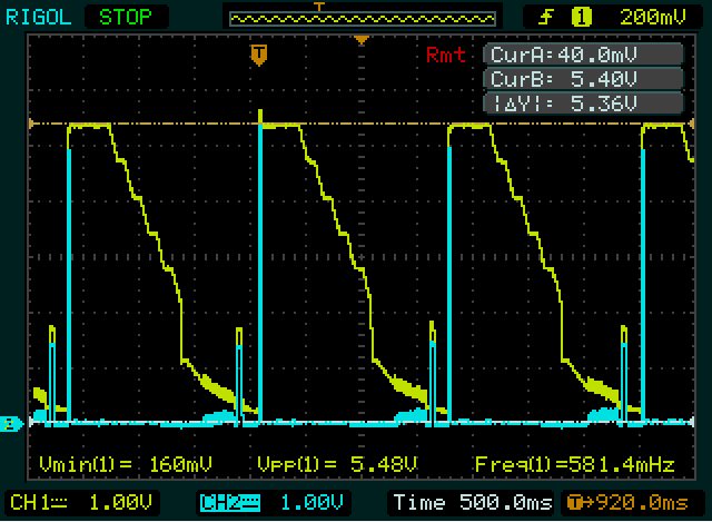
After probing certain signals, VDD is 53.6 Vpp 0.5 Hz, GATE is 0V which leads to switching MOSFET to be off and converter is disabled. Vc oscillates from 15.2 V to 8.2 V at 6.58 Hz for 1 second and then drops down to 0 V for 1.5 seconds, and repeats. 

Is this an issue with the detection/classification? Any help is greatly appreciated.

  • Hi Neil,
    Are you testing with the actual EVM? Was it working originially without the modifications? What are the test conditions? Are you using a PSE? Are you loading the output at startup? Without the T2P signal, how does the load know that it can consume >13W?
  • Hi Darwin,

    I have here 3 boards. 2 EVM's, 1 Rev B which is working, 1 Rev A and a custom board, both of which exhibit the periodic drop of VDD from 53.6 V to 0, at a frequency of .5 - .7 Hz. Both EVM's are not modified, but the custom board is. Using 2 different PSE's, a commerial switch using PoE and a Netgear GS510TP with PoE+. Both PSE's produce the same results. The 5V output has just an LED indicator with a 1K resistor, no other load is connected as of yet.

    While probing VDD-VSS during start up on the custom board, it rises to approx 6 V and then drops back down to 0 V, which tells me its a detection issue.
    While probing VDD-VSS on the working eval board, it does the same and the board does not power up, but if I remove the probes it powers up and D2 and D17 indicate the converter is functioning.
  • Testing with multiple PSE sources, the eval board only has issues with the Netgear GS510TP during probing, but works fine with the other PSE's. 

    Attached is a screenshot of the VDD-VSS output (CH 1) and Vrtn-VSS (CH 2) of the custom board with a PSE that the eval board functions correctly with. The probe is set to 10x attenuation so the voltages are just 1/10th of the actual values. Still not sure why the voltage rises to 53V and drops down only to repeat itself.

  • Hi Neil,
    Try adding some load on the output to meet MPS. Minimum input current should be at least 10mA to keep the PSE on.
  • Hi Darwin,

    By the output are you referring to the 5V output? I connected a load of 333.333 ohms to the 5V output but there is no change as the GATE pin is still low and not oscillating to enable the transformer.
  • Hi Neil,
    I was thinking more like 200mA or so at the 5V output. So ~25 ohms should work.
  • Had a 5 ohm 20 W resistor lying around and tried that, still no change in output, VDD rises to 54 V and falls off.
  • Since the PSE is able to turn on to 54V means the detection and classification is working and thus the PoE section of the PD might be okay. It may be the DCDC converter section that has issues.
    You may need to check the board that the correct components and values are assembled and there are no shorts causing the converter to hiccup. A side by side impedance comparison with the EVM might speed things up.
  • I will continue to investigate the DC/DC converter side, just curious what the changes from Rev A to Rev B of the TPS23754EVM-420 were. We have a Rev A which has similar behavior to the custom board, while Rev B works as expected.

  • Hi Neil,
    Looking into the history of this, the synch FET was changed due to the REVA synch FET becoming obsolete. The new synch FET used is the Si7880ADP.
  • Hi Darwin,

    Is there a PSpice component for the TPS23754 to run simulations for the expected output?

    Thanks

  • Hi Neil,
    Unfortunately, there is no PSPICE model for this PD and there currently is no plan to release a SPICE model.
    SPICE models were only only done for the TPS2378/9
  • No worries.

    Was able to figure out the problem, the Optocoupler in the feedback portion of the circuit was mirrored with the phototransistor and LED were on the opposite sides. Flipping it results in VDD-VSS no longer dropping, and GATE switching at the 250 KHz.

    Thanks for the help.