This thread has been locked.

If you have a related question, please click the "Ask a related question" button in the top right corner. The newly created question will be automatically linked to this question.

LM25066 ESD Question

Other Parts Discussed in Thread: LM5069, LM25066, STRIKE

Using the LM25066 in my design and boards were operating properly, but TEST ESD (8KV)  it stopped working (no voltage seen at the Source pin of FET).

when test over,the board will working.

For my design Vin is fixed to 5V and is always present i.e. Vout is the hot-insertion point. I have a 10mOhm sense resistor between VIn and Sense pins.

when used LM5069, there is no problem,why LM25066?

  • Hi Roy,

    What kind of ESD test is being conducted? Where is the voltage strike occuring? Is there a TVS or ESD clamp protection being used, or are you relying on capacitance + the IC to handle the discharge?

    The LM25066 IC has 2kV HBM and 500V CDM rating which is intended to be safe for manufacturing environment. But my guess is this 8kV may be a more comprehensive test.

    When the test is conducted, do you see the controller shut off and stay off? If so, this could be triggering the circuit breaker function. If the device is set for retry mode (RETRY pin connected to GND) then the LM25066 should wait a period of time and then try turning on again.
    - If I had to guess, I would think this would be occuring since an ESD strike can create large voltage transients which could trigger the CB. One way to mitigate this would be to install an RC filter on the SENSE lines. Check out this application note regarding system transients for hot swap design (particularly Section 3 on page 10):
    www.ti.com.cn/.../slva703.pdf


    The LM5069 does not operated down to 5V, so it may be a different test condition.

    Note that ESD is often a system level test which can be heavily dependent on layout. I recommend this application note for tips:
    www.ti.com.cn/.../slva680.pdf

    Thanks!
    Alex

  • Hi Alex:

    1.ESD test :it not contact the circuit board,it contact the panel of the board ,but there is no electrical connection.

    2.when ESD test , the voltage of the MOSFET (Vg=4.2V) ; when not test , the voltage of the MOSFET normal (Vg=11V).

    3. There is a TVS being used in the board.

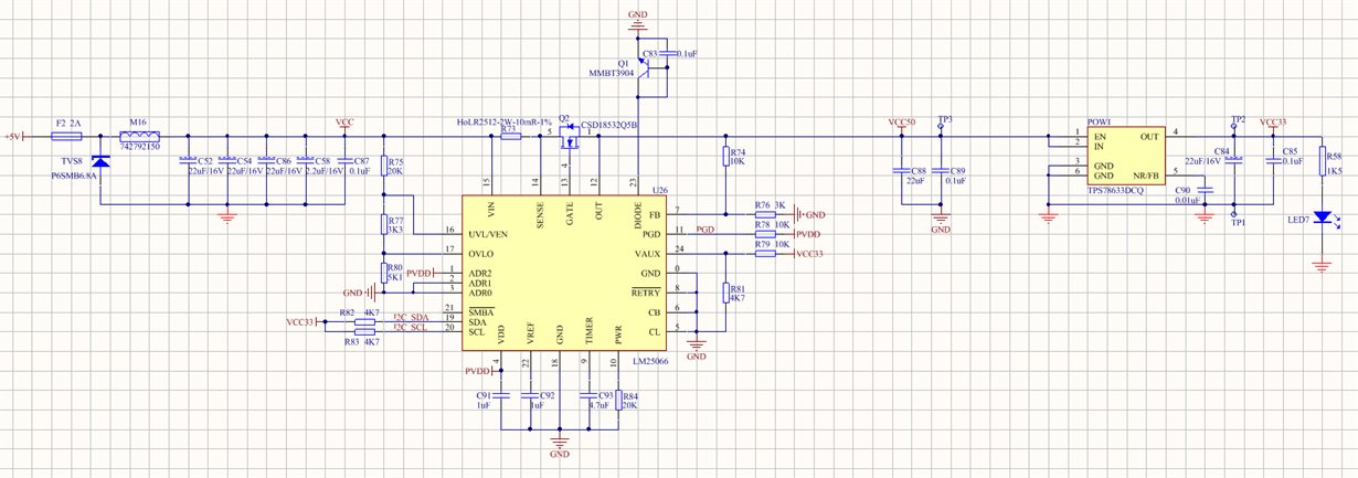
    4. There is a picture of the circuit , there is a different of the gnd symble ,but the gnd of the circuit is the same net.

    please help me check it, thank you.

  • Hi Roy,

    Just to clarify but the device is working ok after the ESD strike, but during the test the LM25066 shuts off power to the load?

    First I would suggest removing R77 in order to disable UV/OV function to see if that resolves the issue.

    If not, I would consider adding an RC filter to the VIN and SENSE pin just as is used in Section 3 of this document (Figure 11):
    www.ti.com.cn/.../slva703.pdf

    My guess is there will be a fast transient on the SENSE lines causing the CB to go off and I cannot tell whether a 1us RC filter would be sufficient to prevent it.

    Thanks,
    Alex
  • Hi Alex:

    1.Just to clarify but the device is working ok after the ESD strike, but during the test the LM25066 shuts off power to the load?

    YES,shuts off power to the load.

    2.First I would suggest removing R77 in order to disable UV/OV function to see if that resolves the issue.

    removed the R77,the result is same.

    3.DO you have other good solution?if adding an RC filter to the VIN and SENSE pin,but do not solve the problem.

    Thank you.

  • Hi Roy,

    Sure there's some additional ways to make the circuit more robust to transients.

    For example, the CB pin can connect to VDD (directly or through a 0ohm). This will give more headroom for transients.

    Also, the VDD cap can be increased from 1uF to 4.7uF. This keeps the VDD supply more stable against noise coupling in and causing a shutdown.

    Those are probably the next two I would start with after the RC.

    However I don't see ESD testing for hot swap circuits very often. Is it possible to connect as oscilloscope during the test, or is that not permitted in the procedure? If it is possible, then looking at VIN, VOUT, GATE, TIMER and triggering on the GATE falling edge should tell a lot. Having a zoomed out waveform and then a zoomed in waveform to see the slew rate of the GATE should tell what block of the IC is turning off the FET (whether it is activating the strong pull down from circuit breaker, or 2mA pull down from UV/OV/current limit for example).

    Thanks!
    Alex
  • Edit: Another way to set the CB to the higher setting without a pin change is to change the register via software (so you don't need to hack up the board). Change bits 1 and 3 in the DEVICE_SETUP register D9h:
    www.ti.com/.../lm25066.pdf

    Note that the device does not have NVM, so it will not save this setting when you lose input power. So you would need to power up the board, change the bits, then do the test. Otherwise you can change the hardware since it will default to the pin setting of the CB pin.

    -Alex