This thread has been locked.

If you have a related question, please click the "Ask a related question" button in the top right corner. The newly created question will be automatically linked to this question.

LM5060 / maximum TIMER pin voltage

Other Parts Discussed in Thread: LM5060

Hi,

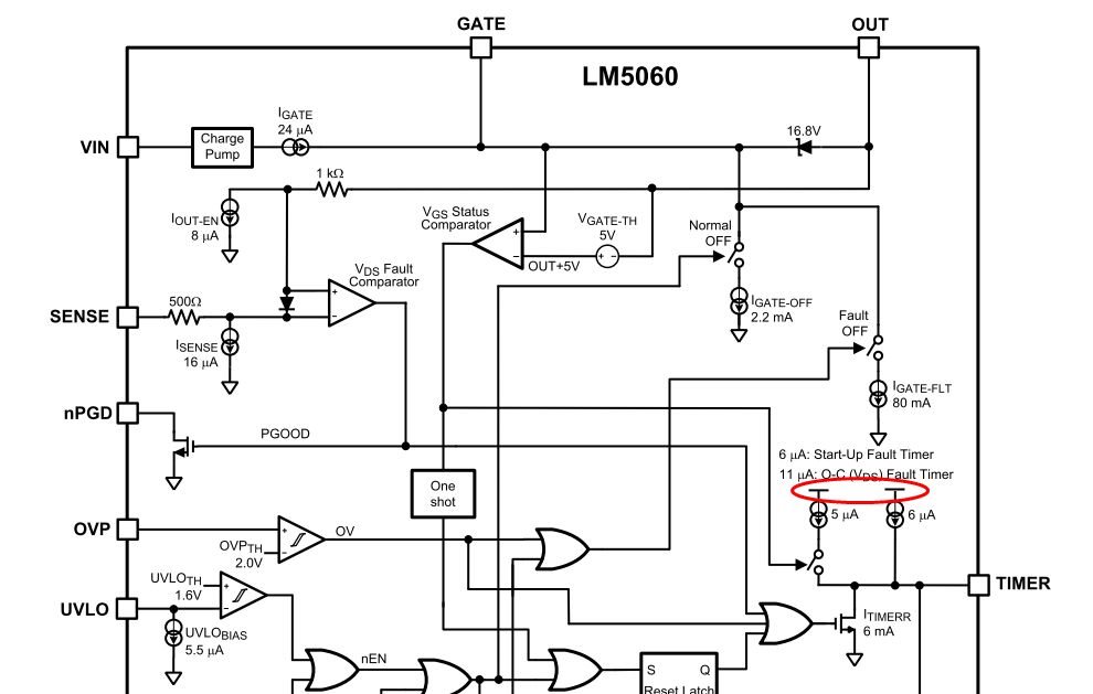
Please let me ask about the source voltage of timer charge current. I'm asking it because I'd like to know by how many voltage the TIMER pin voltage goes up. I guess that it may be the charge pump output, then I'd like to know the maximum voltage of internal charge pump output. 

Best Regards,

Sonoki / Japan Disty

  • Hi Sonoki-san,

    Note that we just released a new LM5060 design calculator tool just 1-week ago! It is live and is available on the LM5060 product page under Tools and Software, otherwise can be found at:

    www.ti.com/hotswap --> "Tools & Software" which is where the design calculator tools for all of our hot swap controllers can be found. This tool can help with the calculations needed to create a design.
     
    To address your specific questions:

    1) The TIMER voltage will not go above the Vtmrh threshold which is 2V typical. Its variation is quite small and can be considered negligible.

    2) The charge pump max voltage is basically spec'd. It would be the Vgate in the datasheet (which is the gate voltage minus Vin, so it is the charge pump output). The voltage is 10V min, 12V typ, 14V max.

    Thanks,
    Alex

  • Hi Alex,

    Thank you for your comment. I could find LM5060 Design Calculator in its product folder. I'll also utilize it.

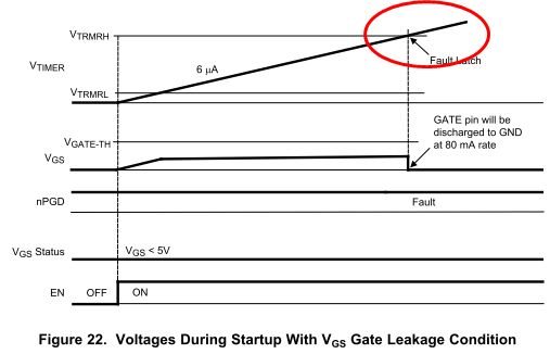
    Regarding your answer for 1), I also thought that the TIMER voltage will not go above Vtrmrh but the image in Fig22 continue to rise after reaching Vtrmrh. Does this image not show actual behavior of TIMER voltage?

    Best Regards,

    Sonoki

  • Hi Sonoki-san,

    Thanks for bringing this to our attention. I understand the concern and will speak to our IC design team for additional guidance. Will try to get back to you tomorrow, otherwise early next week.

    Thanks,
    Alex
  • Hi Alex,

    Thank you for your support. I'm waiting for your update.
    The background of this question is that the customer hope to reduce voltage rating of timer capacitor though EVM uses 50V rating.

    Best Regards,
    Sonoki
  • Hi Sonoki-san,

    We will need to test this in the lab on monday using an EVM. Will get back to you on 8/22 (Dallas time).

    Thanks!
    Alex
  • Hi Alex,

    I appreciate for your support. I'm waiting for the result of your bench test.

    Best Regards,

    Sonoki

  • Hi Sonoki-san,

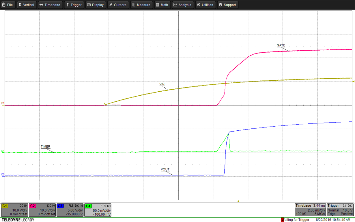
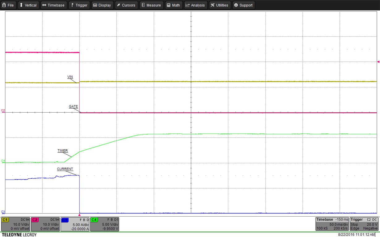
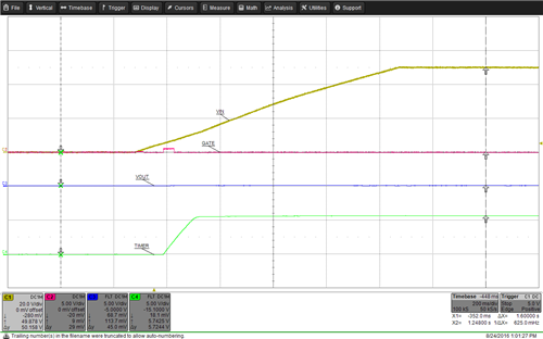
    So we tested this in the lab. First, we captured a normal startup waveform, where the TIMER only charges slightly:

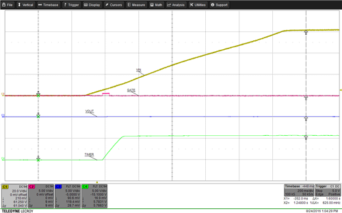
    Next, we added a small signal diode from gate to source of the MOSFET, to prevent it from reaching 5V Vgs. This allowed the TIMER to continue to run, and it reached a value of about 5.8V:

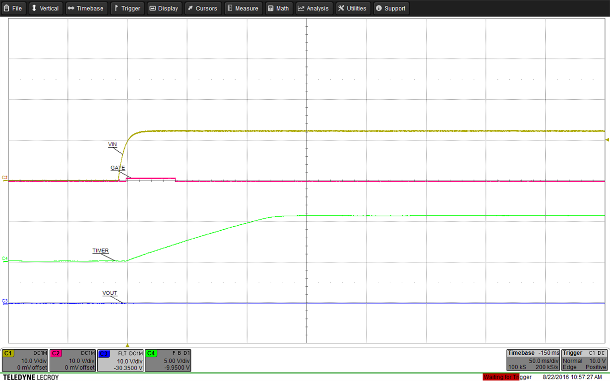
    Finally, we captured a wavefom of an overcurrent event. The TIMER also reached a value of about 5.8V:

    Overall, the TIMER does not discharge when it reaches Vtmr-high since the device is latch off and waits on the Vin, EN, UV or OV signal to cycle before starting up again.

    In summary, we would recommend a standard ceramic capacitor voltage rating of 16V or 25V

    Thanks!

    Alex

  • Hi Alex

    Thank you for providing capture of TIMER pin behavior at startup. It reaches around 5.8V and it may be internal bias voltage used for timer charge current source. Is my understanding correct?

    Best Regards,
    Sonoki
  • Hi Alex,

    Let me ask one more question. Does this TIMER pin voltage not depend on VIN? I'd like to know if it will be also 5.8V at 65V input (Vin_max) though you checked it with 12V input.

    Best Regards,
    Sonoki
  • Hi Sonoki-san,

    You are correct, it is an internal bias voltage. It does not vary much over VIN range.

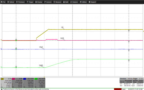
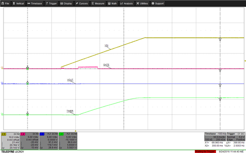
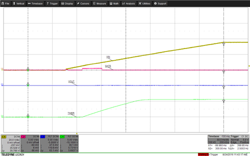
    We took measurements yesterday across VIN using the same diode on Vgs technique (and we disabled UV/OV):

    Vin            V Timer Max
    6V 4.56V
    20V 5.65V
    35V 5.73V
    50V 5.74V
    64V 5.78V

    Waveforms below for the different VIN range:

    Thanks!

    Alex

  • Hi Alex,

    I appreciate for your effort !!
    Let me close this question.

    Best Regards,
    Sonoki