This thread has been locked.

If you have a related question, please click the "Ask a related question" button in the top right corner. The newly created question will be automatically linked to this question.

Problem with TPS2492

Other Parts Discussed in Thread: TPS2492

Hello.


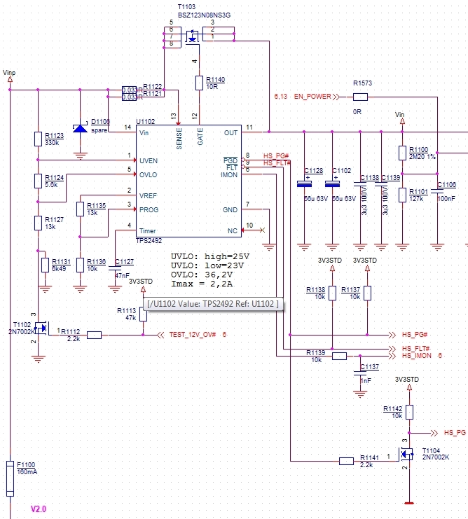
in our board we use the TPS2492L as eFuse. The UV/OV conditions are: undervoltage switch on (rising) = 25,5V, undervoltage switch off (falling) = 23,4V and overvoltage = 36V. With I typ = 3,03A. If I increase the input voltage (at 25,5V) the controller switch on the FET only at half, I can measure about 6V on source. Above 25,7V input voltage the FET will be switched fully on and I can measure the input voltage. Is this behaviour normal and what can I do to avoid this?

Thank you for your help.

BR

martin

  • Hi Martin,

    Thank you for using our part. Because the UV pin is hysteretic, it should turn on or off (not in between) when reaching these thresholds. Here are some questions for you:

    1) Where are you measuring Vsource? Is it from Gate to Source (Vgs) or from Source to GND (Vout)?

    2) Does the voltage stay at 6V during steady state?

    3) Could you provide waveforms of Vgate, Vout, Vin,  and Current In (make sure that the current in is being probed after any capacitors at the VIN pin, and not before). Trigger the waveforms to happen right  when Vin= 25.5V (you could probably trigger the gate here), and separate waveforms of when Vin= 25.7V.

    We also have a new calculator tool for the TPS2492, which makes it simpler to design and use. It can be found at www.ti.com/hotswap ==> Click on "Tools & software" ==> then click "Hot Swap design calculator tools" ==> then click on "TPS248x/TPS249x Design Calculator". 

    We also have step-by-step video tutorials at www.ti.com/hotswap --> "Support & Training".

    Finally, all the equations and methodology are explained in our application note at www.ti.com/hotswap ==> "Technical Documents" ==> "Robust Hot Swap Design".

    Best Regards,

    Aramis P. Alvarez

  • Hello Aramis,


    1) I do the measurement at Vout (Pin 11).

    2) Yes

    3) Yes
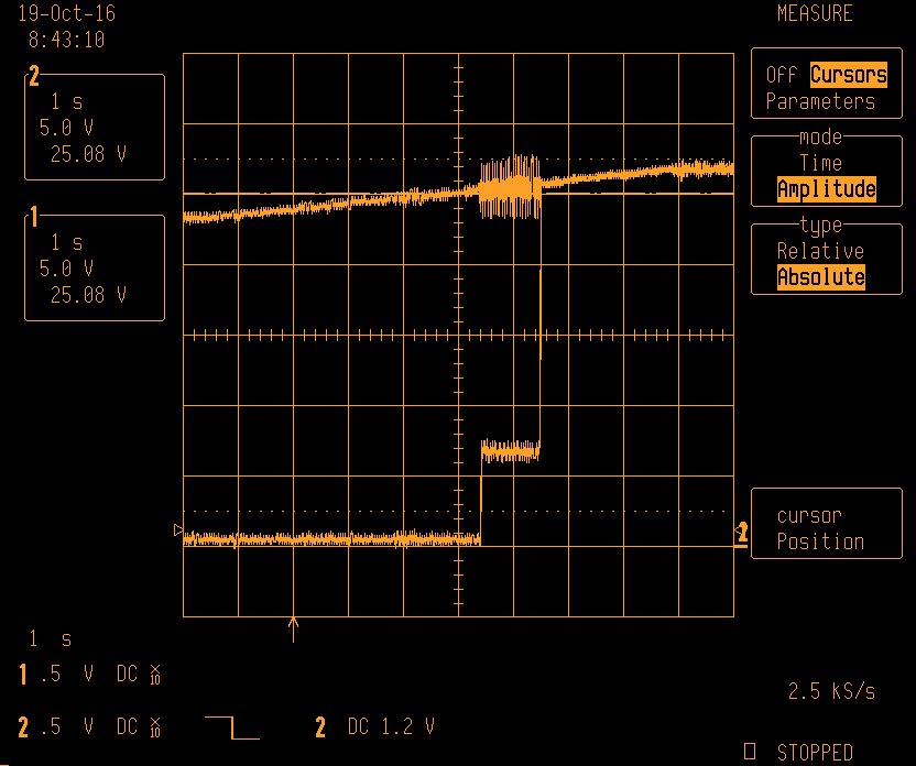
    First: With Rsense = 17mR (0,033R || 0,033R) Chn. 2 = Vin (risign from 23V to 27V); Chn. 1 = Vout on the output capacitor. During 25.2V and 25.7V input you can see the step.

    Second: The same condition with Rsense = 22mR (0,068R || 0,033R). The switching behaviour ist corret.

    I changed only the Rsense and no other components.

    BR

    martin sauer

  • Hi Martin,

    Thank you for providing the waveforms above, this helps a ton. It seems to me that there's a lot of oscillations happening on the Vin rail during the transition region,  causing Vgate to do the same. This could be the power supply or test setup but I'm not so sure. Please provide for me two things:

    1) Could you probe the Vgate pin in addition to Vin and Vout and show all three on the same waveform for both scenarios above? (Rsense = 17mOhms and 22mOhms)

    2) Please provide another waveform zoomed in on the transition region where both Vin and Vout are oscilating. Zoom in enough that we only see 3-4 oscillations on the waveform.

    Best Regards,

    Aramis P. Alvarez

  • Hi Aramis,


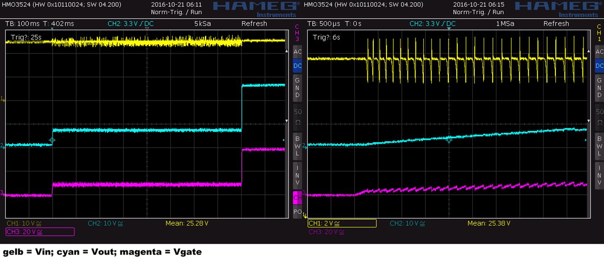
    first picture with Rsense = 17mOhm:

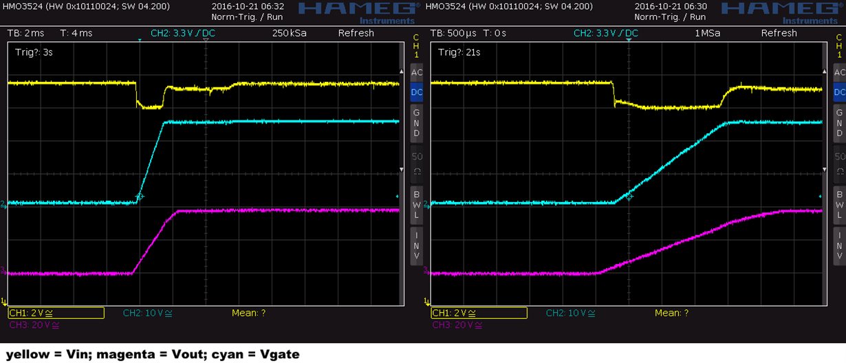
    Second picture with Rsense = 22mOhm:

    BR


    martin sauer

  • Hi Martin,

    Thanks a bunch for providing waveforms above. Its seems that the power supply might be the issue here. On both graphs, the Vin rail collapses when current starts to conduct. The top graph has a higher current limit and therefore has a bigger droop on the Vin rail. One possible theory here is that the Vin rail is drooping low enough to get into UV lockout. This event will turn off the gate. Then the Vin rail goes back up again, turning on the gate again. This happens back and forth until the Vin rail is increased and the droop stays above the UV threshold.

    You could possibly try two things

    1) Try to do the same experiment with a different power supply (I really do think that the power supply might be the issue here).

    2) If you don't have another power supply, add an input cap to the Vin rail. This will help stabilize your rail and prevent it from drooping so low. I would start off with a 10uF-100uF cap and see if that works. 

    Best Regards,

    Aramis P. Alvarez

  • Hi Aramis,

    I tried an additional capacitor at Vin an the problem still improves. I think this is the solution.

    Thank you for your help.

    BR

    martin sauer