This thread has been locked.

If you have a related question, please click the "Ask a related question" button in the top right corner. The newly created question will be automatically linked to this question.

TPS2490: TPS2490 starts up with enable pulled low

Part Number: TPS2490
Other Parts Discussed in Thread: CSD19536KTT

Hi,

We use this device to switch 50V into a load. Circuit used as attached.

Strangely, with enable pulled down to ground (and no active source driving it high), the N-Channel FET source still appears at 50V. The gate voltage is also maintained at 50V. If we connect enable pin to input VCC (50V), the gate goes to 60V, but the output is un-affected.

We understand from datasheet that there should be no output with TPS2490 enable low. Can you please check?

Regards

Gaurav

  • attachment was missing in last message.

    Regards

    Gaurav

  • Hi Gaurav,

    Thank you for providing the schematic. Could you also please provide and attach the design calculator tool with this device? This will help review and troubleshoot your design, and would greatly speed up the back-forth communication of questions we would have for information needed for the review (such as total output cap including anything connected downstream from the output node, which may not be shown on a partial schematic).

    You can find it by going to www.ti.com/hotswap ==> click on “Tools & software” ==> then click on “Hot Swap design calculator tools”

    For help on filling out the cells on the excel spreadsheet, our team created video tutorials on how to fill out the hotswap design calculator spreadsheet. They explain cell by cell what each one means and how to enter the correct value. The videos are at www.ti.com/hotswap ==> Click on “Support & Training” tab.

    Also, if you could please provide waveforms (showing the issue) of the following signals: 

    a) Vin

    b) Vout

    c) Vgate

    d) Venable

    e) Current In

    If you have access to only 4 probes, then could they take two waveforms showing the same event, replacing Current In with Venable? Thanks

    Best Regards,
    Aramis P. Alvarez 


  • Hi Aramis,

    I tried filling the excel as best possible with our circuit info. Can you please see the attached.

    Please give some time to arrange the waveforms, meanwhile you may review the excel.4370.TPS249x_8x_Design_Calculator_REV_A.xlsx

    Regards

    Gaurav

  • Hi Gaurav,

    Thank you for attaching the excel tool. In reading your first message again, it sounds like your FET might be fried. You could try to check it out by measuring the resistance from Source to Drain. If the resistance is very small, then that could be it. If that's the case, I would recommend a FET with a stronger SOA curve, such as the CSD19536KTT. 

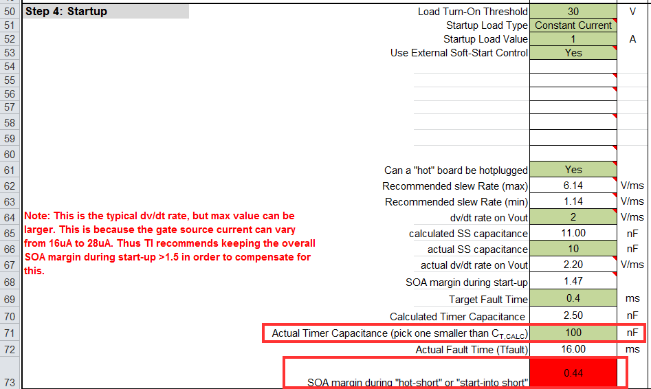
    Also, I noticed on the calculator tool that the application is drawing about 1A of current during startup, but there's a dv/dt circuit to control the inrush current to around 220mA (100uF*22uA/10nF = 220mA).

    What type of 1A load is being drawn (electronic load, resistive load, DC/DC load)? Would you be able to use the Power Good pin in order to turn on devices downstream? This will give the device the opportunity to start up and charge the output cap before current is being drawn :-)

    I hope this helps.

    Best Regards, 

    Aramis P. Alvarez

  • Hi Gaurav,

    I noticed on the calculator tool that the input for the Timer Cap was set at 3nF, but on your schematic, it shows the Timer Cap = 100nF. If a hot-short or a start-into-short test was done, then the SOA margin is being violated (below 1.0). This will surely fry the FET (look below). What type of tests have you completed before you noticed the board not working properly? If you could answer this question as well as the ones from above that would be great.

    Best Regards,

    Aramis P. Alvarez

  • Hi Aramis,

    We found out that the FETs were not correctly mounted, the circuits works fine now. However, let me read in detail the timer cap requirement and get back to you.

    Regards

    Gaurav

  • Hi Aramis,

    We have gone through your suggestion and now modified the fault timer capacitor to 2.2nF to have a correct SOA margin.

    Thanks for your help!

    Regards

    Gaurav