This thread has been locked.

If you have a related question, please click the "Ask a related question" button in the top right corner. The newly created question will be automatically linked to this question.

LM5069: LM5069 Hot Swap - Getting finer resolution of current sense at high current limits

Part Number: LM5069

Hello,

I currently have a design for high current limit which works well for me. I am using a LM5069 with a current limit of 0.055V / 0.002 Ohms = 27.5A
I would like to be able to scale this current limit a bit higher but of course at such low ohmic sense resistors, the only mainly available values
in this range of 1 milliohm would double it. If I am trying to achieve a CL of 35A, for example, would the following modification circuits work?

In the above example I took my signal from my 2 milliohm sense resistor and divided it with a voltage divider but with
a small effective resistance

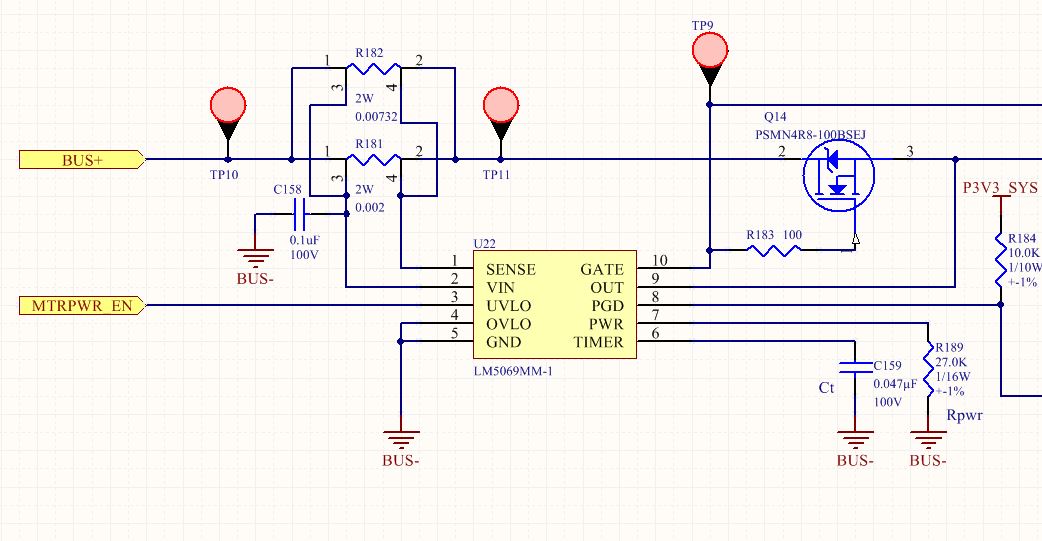
In the second example above, I just added a second kelvin resistors of 7.32 milliohm for a total effective sense resistance of 1.57 milliohms.
0.055V / 0.00157 Ohms = 35A

Can someone tell me either of the above is okay? Or both if that is the case? If both are okay, is one preferrable to the other?

Thanks.
Dan

  • Hi Dan,

    You're in luck! We have a section in the datasheet that explains how to implement the voltage divider that you described above (bottom of page 18, top of page 19). I recommend the first option pictured above, but please change R182 from the VIN pin and place on the SENSE pin (look below). I would also recommend lowering the resistance value from 100Ohms to 10Ohms. The datasheet (in the same section) explains in detail the reason for both of my recommendations.  

    One quick note, the voltage across the Rsense element will be around 70.07mV, and the power across the 2mOhm sense resistor just went up. Make sure the power rating satisfies the newly added voltage divider (I^2 * R = 35A^2*2mOhms = 2.45W). 

    Also, I'm not sure if you know this but we have these nifty calculator tools that help our customers with their design. The tool also has a cell to calculate a resistor divider, for those that choose to do so. You can find it by going to www.ti.com/hotswap ==> click on “Tools & software” ==> then click on “Hot Swap design calculator tools”

    For help on filling out the cells on the excel spreadsheet, our team created video tutorials on how to fill out the hotswap design calculator spreadsheet. They explain cell by cell what each one means and how to enter the correct value. The videos are at www.ti.com/hotswap ==> Click on “Support & Training” tab.

    I hope this helps :-)

    Best Regards, 

    Aramis P. Alvarez

  • Hi Aramis,

    Thank you for your response. I just realized that I had an outdated datasheet.

    I see that you recommended the first option according to the datasheet. But the second option should work, correct? 

    This second option would save me having to use a bigger resistor package at the expense of putting down a second
    resistor of the same package size. Just nice to know if I have this option available to me.

    Thanks.

  • Hi Dan,

    The second option would work but could be less accurate. When paralleling two sense resistors, if the layout doesn't have differential routing, this will add extra resistance to the already small resistance of the sense resistor. Also, the solder might have a different profile for each sense resistor, which further degrades the accuracy.

    I do want to point out that the 2nd option will work, but the 1st option has better accuracy and is the recommended solution for current sensing. I hope this helps :-)

    Best Regards,

    Aramis P. Alvarez