This thread has been locked.

If you have a related question, please click the "Ask a related question" button in the top right corner. The newly created question will be automatically linked to this question.

TPS2373: inquiry about MPS of the TPS2373-4

Part Number: TPS2373
Other Parts Discussed in Thread: TPS23753

Hi team.

My customer and me has a lot of questions about the MPS of the TPS2373-4.

1. Customer's question : How should I configure the circuit of the TPS2373-4 to operate the MPS_Duty of the red box shown in the table below to 26%?  


  - My question :  If I look at the data sheet contents, I know that you will check the type of PSE automatically.

                            However, there is no detailed description of how the TPS2373 can check the PSE's Type. Please explain.

2. Customer's question : Is it appropriate to connect 1.3 ㏀ between the AMPS_CTL pin of the TPS2373-4 and VSS to activate the function of the red box in the table below?  

  - My question :  Looking at the datasheet, RMPS appears to use  between 1k and 12k when IRTN is 20mA or less. Is that right?

                            And I know that RMPS can get the integer through the formula below.

                            Then, is IMPS value equal to IRTN value?  If so, can I calculate the RMPS value by setting the minimum current to the IMPS value when there is no load?


                            And in the formula for calculating PRMPS, please check why the denominator is multiplied by the duty cycle.

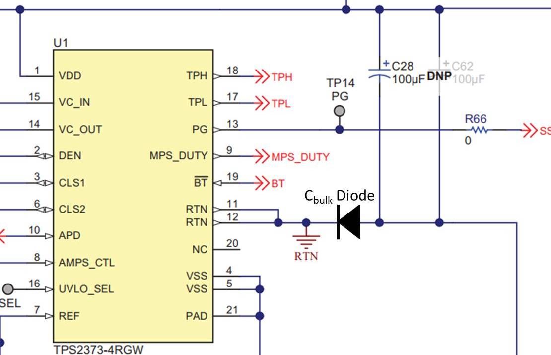
3. Customer's question : What is Cbulk Blocking Diode in a Datasheet or EVM circuit? And Please describe in detail what is the 'PSE voltage step-down events'. 

    - Refer to the red box in the table below.

4. Customer's question : How to set the Automatic MPS function satisfying PSE Type 1 ~ 4?

Thank you.

  • Hi Charles,

    Let me do a little research & get back to you soon.

    Thanks,
    Tom
  • Hi Tom.

    When do you can reply?
    Customer requests reply verification.

    Thank you.

  • Hi Charles,

    1. 26% is automatically generated when a Type 1 or 2 PSE is detected. The PSE generates the class fingers by sending 18V to the PD. Each time, the PD responds with its requested power by sending 2.5V through its selected class resistor (CLSA or CLSB) back to the PSE. The number of class events sent to the PD tells the PD what type the PSE is.

    When the PSE sends a single class event (18V) & the PD responds with a 1,2, or 3 class pulse, then the PSE knows to provide type 1 power & no other class events are needed.

    If the PD responds with a class 4 pulse after the first class event, the PSE will send a 2nd class event to tell the PD that it can supply type 2 power & the PD responds with its class current pulse to confirm.

    2. AMPS_CTL resistor controls the current amplitude, not the duty cycle. To control the duty cycle, do as shown in the middle column.

    Rmps is the resistor between AMPS_CTL & VSS. Imps is the current sent through Rmps & back to the PSE when AMPS_CTL = 24V. Irtn<20mA means there is no load.

    For the AMPS_CTL calculation: The denominator should not be multiplied by the duty cycle. Thanks for catching that :)

    3. Let me get back to you.

    4. 26% will automatically be generated when type 1 or 2 PSE is present. The other duty cycles for type 3 or 4 will depend on how the PSE is configured.

    Best,
    Tom
  • 3. The Cbulk Diode is between the bulk cap & RTN with the cathode facing towards the input. A "PSE Voltage step down event" is just a catch all term for a sudden reduction of voltage (in this case, greater than -0.4V).
  • For more info on the "PSE voltage step down event", see section 8.4.6.2 in the datasheet for TPS23753: www.ti.com/.../tps23753a.pdf

    - Tom
  • Hi Thomas

    Can I show the exact location of the Cbulk Diode in the schematic? Or can you give us some resources you can refer to?

    And in question # 4, is there any way to set all MPS functions automatically in PD?

    Thank you

  • Hi Charles,

    You need to specify the the MPS functions. AMPS_CTL & MPS_DUTY need to be selected by the designer.
    Leaving AMPS_CTL open will disable auto MPS.
    Leaving MPS_DUTY will select 5.4% duty cycle.

    Best,
    Tom
  • Hi Thomas,
    The customer has three additional questions below.

    1. When PSE is type1-2, what should Rmps values be applied?

    2. Please tell us the role of C_bulk.

    What is the function of C_bulk that allows you to choose a shorter MPS duty cycle?

    And if you use C_bulk, is not there a limit to the value of C_bulk?

    3. If I set MPS Duty-cycle to 5.4%, can I support all PSE types without additional setup?

    Then, does this mean that '5.4% or longer' in Table 5 supports all MPS Duty-cycle greater than 5.4%?(5.4%, 8.1%, 12.5%)


    Thank you.

  • Hi Charles,

    1. For choosing the Rmps value, you take the same considerations you would with a .bt system: How little current is drawn when the load is detached? This depends on the system. When you find that current level, you know you need to have an Auto MPS current pulse big enough to exceed it.

    2. The bulk cap is a required part of the power converter. The issue is that the auto mps pulses can eat into the charge on the capacitor. The blocking diode is there to prevent this leakage current.

    3. Any of those MPS duty cycles will work with any PSE (that is compliant with the .bt standard). The real concern is that the appropriate duty cycle is selected according to table 5.
  • Hi Thomas,

    I'm sorry. There was an error in question # 2.

    Please revise and retry as below.

    2. Please tell us the role of Cbulk_diode.

    What is the function of Cbulk_diode that allows you to choose a shorter MPS duty cycle?

    And if you use Cbulk_diode, is not there a limit to the value of C_bulk?

    And I will add it to the third answer.

    If I open the MPS_Duty Pin, is it possible to support from 5.4% duty to more duty?

    My conclusion is that my customers want to know how to set the MPS_Duty Pin and AMPS_CTL pins to support all PSE Type and all MPS_Duty Cycles.

    Please answer.

    Thank you

  • Please answer.
  • Hi Charles,

    1. The TPS2373 will know what PSE it is connected to. If a type 1 or 2 PSE is connected, the PD will automatically output 26% regardless of how MPS_DUTY pin is configured. If a type 3 or 4 PSE is connected, the PD will know and check how MPS_DUTY is configured and will output the associated duty cycle.

    2. Cbulk diode and its location is described below. Like it states, it's typically seen in UPOE or dual PoE applications however, if you do not want the bulk cap to effect the MPS duty cycle because lower duty cycle (low standby power consumption) is important, then you can add a diode as described below. The bulk cap can take away at the auto MPS pulses that goes to the PSE to maintain power. This means that at lower duty cycles it's possible for the PSE to remove power unless the table is followed. Adding the diode blocks any current from flowing through the cap so lower duty cycles are possible.

    Note the diode helps prevent cbulk affecting the auto MPS duty cycle. Unrelated, in general if you go too high of bulk cap, the longer a PD will be in inrush during startup. This can cause the PD to heat up and possibly reach thermal protection. This is described in the many E2E posts and can be searched. I have not seen an application yet that needed a bulk cap larger than 300uF.

    If you open MPS_Duty pin, the duty cycle will be 5.4% and not any more.

    3. The Cbulk blocking diode can be either between VDD of the (diode anode) and the positive of the bulk electrolytic cap (diode cathode). Or between RTN (diode cathode) and negative of the bulk electrolytic cap (diode anode). This is also shown in Tom Amlee's picture in the previous post. It's not often that these diodes are here. Typically you will see them in forced UPOE applications or dual PoE applications.

    The 'PSE voltage step-down event' is as suggested by the footnote a very rare occurrence where a PSE switch's power supply can droop (step-down) during a switchover event. In which case, a lower duty cycle may cause a skip in MPS pulse. The note and the table was added to ensure that for lower duty cycles (to save on standby power) the PD system should be known by the designer. And for larger bulk caps with lower duty cycles, the PSE system should understood. Otherwise, it's highly recommended to use the 12.5% duty cycle to ensure all bases are covered.

    4. As described in #1. Automatic MPS is automatic and will adjust accordingly depending on what type PSE is connected to the PD.

    If you're customer wants to support all types of PSE, I recommend sticking to the 12.5% duty cycle and keep the bulk cap less than 120uF.

    Regards,
    Darwin