This thread has been locked.

If you have a related question, please click the "Ask a related question" button in the top right corner. The newly created question will be automatically linked to this question.

LM5072: feedback loop component "TL431" damage

Part Number: LM5072
Other Parts Discussed in Thread: TL431, , PMP8803, TLV431

Hi,

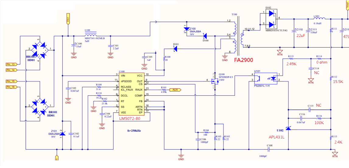
We design an 802.3at PD with 12V output. I suffered from a reliability issue that 15% of the PDs will malfunction within

2 ~ 4-month due to damage of TL431 (in SOT23-3 package). The output of PD is used as power source of consumer apparatus 

which are not inductive and consumed around 10 ~ 15-Watt.  We did experiment by shorten the output of PD to 

emulate over-current. The results show that over-current protection scheme of LM5072 will be activated and there is no damage on TL431.

The PD design is based on the reference design of LM5072 for 802.3at. Do you have any clue?

  • Hi David,

    I have yet to damage the reference component in our TI designs. The LM5072 is a much older IC and its reference designs are quite dated. However, looking at the schematic, what catches my eye is that I don't see any secondary softstart. In addition, for 12V we typically will have some extra biasing current of the reference. Lastly, the compensation network looks questionable with the 100k ohm resistor. I wonder if its a reliability issue with startup (speculating)?

    For comparison, what we currently recommend for 13W/12V that has been used in many projects at high volumes is the PMP8803. It has the what is described above. Please see below link. Thanks!
    www.ti.com/.../slvrb28.pdf
  • Hi Darwin,

    Thanks for your reply. I am trying to figure out what are secondary soft-start and extra biasing current for reference.

    Firstly, do you mean that secondary soft-start consist of  "R16, D12 and C22"? Do you have any article explain it?

    I would like to know what is the issue if the soft start is not existed. Secondly, dose the extra biasing current is

     referred to a resistor cross the photo-diode? I  heard that the biasing resistor is used for applications with low output voltage

     such as 5V. I am not sure how to associate the damage of TL431 with insufficient bias current. The third, I agree that improper compensation

    may damage the component  of the loop so I will check the compensation loop.

    Best Regards,

    David

  • Hi David,

    That's correct, it is R16-D12-C22. There is no article that explains it however it simply slowly ramps up the reference through the RC time constant through the lower diode. The higher diode helps to discharge the cap at turn off. It acts to help prevent overshoot during startup. This is used on all our PoE TI designs and EVMs.

    At lower output voltages we use the TLV431 which has a lower reference voltage (1.25V) so the opto's biasing current is usually enough and we don't need an extra biasing resistor. For higher output voltage like 12V, we use TL431 (2.5V reference) and need R100 in PMP8803.

    If might be good to look at the VOUT startup waveform from one of the boards that are failing? (after the reference was replaced). You can test with the no load and full load and different input voltages to see if you can catch any unusual waveforms.

  • Hi Darwin,

    Thanks! I will verify the dynamic behavior of the output.


    Best Regards,

    David