This thread has been locked.

If you have a related question, please click the "Ask a related question" button in the top right corner. The newly created question will be automatically linked to this question.

TPS2378: Issue while connect 2pcs TPS2378 EVM with AC adaptor to PSE(different port)...

Part Number: TPS2378

Dear Sirs,

My customer connect 2pcs TPS2378 EVM with adaptor to 1 PSE at same time, and issue occurred.

1. connect 1st EVM with adaptor attached to PSE port 1

2. connect 2nd EVM with adaptor attached to PSE port 2

3. 1st EVM will lost power and start to re-communicate with PSE

4. finally only 1st EVM will seen in system

5. 2nd EVM still has power from PSE

6. after remove adaptor, everything is OK

7. customer use 3 type PSE for test and face same issue

ISON (IS-508P-2F-6)

ZyXEL (GS1100-8HP)

PLANET (WGSD-10020HP)

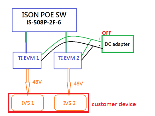
8. customer function block as below


Please help to give me idea to address this issue.

Thanks.

  • Hi Peter,

    I am currently away, but I will look into this when I get back on Friday.

    Thanks,
    Tom
  • Dear Tom,

    Is there any update?

    Thanks.

  • Hi Peter,

    Can you send over a schematic? Also, a couple questions:

    - Is the load attached during inrush? How much current is drawn?
    - How does VDD-VSS look during startup when the PSE is connected? How is class & detection?
    - Does this failure occur with one connected or both? Are they starting up at the same time?

    Thanks,
    Tom
  • Hi Tom,

    Please refer to below for customer reply.

    Thanks.

    - Is the load attached during inrush? How much current is drawn?

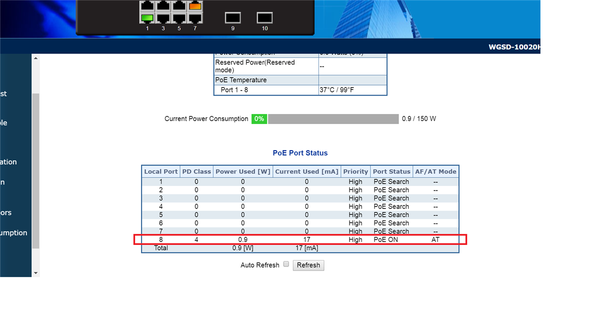
    2 board / 17mA

    - How does VDD-VSS look during startup when the PSE is connected? How is class & detection?

    only shows 1port/ class 4

    - Does this failure occur with one connected or both? Are they starting up at the same time?

    When more than one, it will happen. They are not starting at the same time~

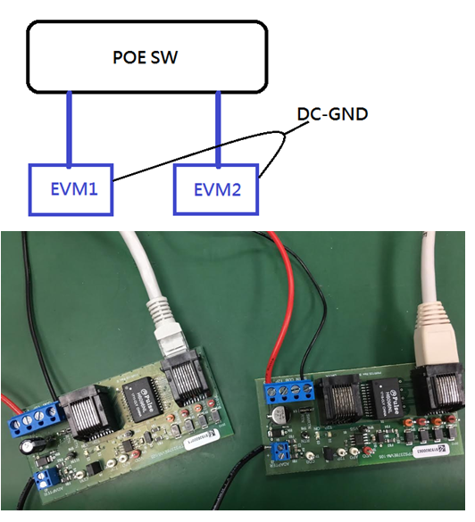
    Here is hardware test configuration. You can also use 2pcs EVM for question duplicated with it.

  • Peter,

    So when the adapter is not turned on, then both PD controllers are able to pass detection & class, then power on? Can you clarify?

    No need for a schematic as you are just using the EVM.

    Some questions about that picture:

    - How have you configured J5?

    - Are you shorting VDD to VDD & RTN to RTN on each board using those red & black wires connected to the J6 header?

    I'm asking a colleague & will get back to you.

    Thanks,
    Tom

  • Peter, Just to be sure Tom's reply was clear, we are awaiting your replies to our questions before we can properly proceed and advise you.

    Thank you for considering PoE products from TI,
  • Dear Sir,

    The reply for question as below.

    BTW, I think it is also a good way and helpful if we can show how to connect 2 EVMs to PSE and work fine to customer.

    Thanks.

    EVM1 board J3 (-) connect to  EVM2 board J3 (-)  (black  wire)

    VDD and RTN are not connect.

  • Peter,

    Intially, what you have told me is that the customer could not successfully power on the PDs with the adapter connected. Now, when an adapter is connected to the adapter input (J3), the APD pin is raised above 1.5V which then turns off the RTN-VSS Hotswap FET which disconnects the PoE ethernet input.

    It makes sense that the PDs are able to power on with the adapter turned off. The APD pin is not being raised. I do not recommend attached to the adapter to J6. Going forward, try testing with the J5 shunt left open & the load attached to VDD & RTN on the J6 output terminal.

    That being said, do you want to be able to power on with PSE with a turned on adapter still connected & be able to fall back to adapter power when PSE is turned off (PoE priority)? If so, you will need to modify your circuit according to the recommendations in section 3.2 of SLVA306A. The TPS2378 EVM is current configured for adapter priority.

    Try it out & let me know what happens under these conditions. If I have additional comments, I will reply to let you know.

    Thanks,
    Tom
  • Hi Tom,

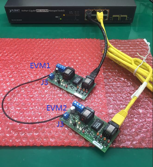
    Let me explain the last connection picture!

    After clarify with customer, this is only for detect issue, the power source switching is no problem with them.

    follow up connection picture with 2 EVMs.

    1. EVM1 plug to PSE  --> PSE detect EVM1 and provide power OK.

    2. After EVM1 existing, plug EVM2 to PSE  --> PSE cannot detect EVM2 but only EVM1, then PSE provide power to both EVMs

    3. unplug EVM1 only  --> PSE detect EVM2 and provide power OK.

    4. replug EVM1 back  --> PSE cannot detect EVM1 but only EVM2, then PSE provide power to both EVMs 

    Is this symptom normal or not?

    if no, how to fix it?

    Thanks.

  • Peter,

    Real quick: do the PDs successfully detect, classify, then power on when they are not connected together (RTN shorted together)?

    I find it very curious that the TPS2378EVM-105 has addition circuitry for switched RTN or OR-ing a 2nd EVM for UPoE, but does not mention our app note for non-standard dual PD designs, http://www.ti.com/lit/an/slva625a/slva625a.pdf.

    Your design looks very similar to the forced four-pair UPoE design on page 2. My first observation is that you will need to populate the diode D9, short J5, and connect the RTN at J6 between the two EVMs in order for both PDs to power on successfully while connected together.

    - Tom

  • Hi Tom,

    After customer testing, it seems same with before.(PSE only detect 1 EVM connected and both EVM can get power from PSE)

    However, it seems to connect 2 EVMs in parallel and that is not customer want.

    What customer want to do is, from PSE GUI, they can know each PD port connection status and monitor every PD power consumption which plugged on PSE.

  • Hi Peter,

    If you short the two RTNs together, the first PD successfully powers on, but the 2nd EVM fails detection because the diode bridge on the 2nd PD is back biased by the 48V applied to the first board. See the top of page 7 of slva625a.

    Q9 & Q8 on the figure 3 schematic (slva625a) need to be in place so that the PDs can detect & classify independently. Alternatively, these can be diodes.

    Regards,
    Thomas A.