This thread has been locked.

If you have a related question, please click the "Ask a related question" button in the top right corner. The newly created question will be automatically linked to this question.

CSD17312Q5: Peak voltage at switching node over VDSS

Part Number: CSD17312Q5
Other Parts Discussed in Thread: CSD17510Q5A, CSD18510Q5B, CSD18512Q5B

I made a synchronous rectification circuit by CSD17510Q5A(high side) and CSD17312Q5(low side) with 24Vin.
Its switching frequency is 500kHz.
There are measurable ringings at the switching node of my circuit and the peak voltages of them are about 35V.
The duration of the peak over 30V is less than 5ns and its peak is not 'flat-topping'.
I think CSD17312 is not in avalanche mode. Is that right?
Are there any problem about the MOSFET in my circuit?

Best regards

  • I am reaching out to the apps team on this one - they may recommend using 40V FETs instead.
  • Here is the response from our apps team:

    "He needs to make sure he has an accurate waveform. With fast dv/dt slew rate, the measurement is sensitive to probe loop size and measurement points. The best way is to use a differential probe with long horn tip to measure right on the device pins.

    Regardless, the ringing is too high. The design needs to be improved to reduce the ringing peak with some margin."

  • Dear Brett,

    Thank you for reply.

    I wanted to use 40 volt FET at first but I could not.  Because RDS(on) and Qg of it were higher than expected.

    So I  want to continue to use CSD17312, if possible.

    Now I got the waveforms of the switching node.  I used single-ended probe with very short ground wire.

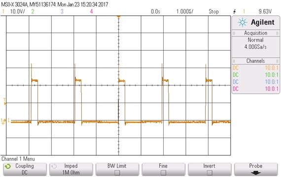
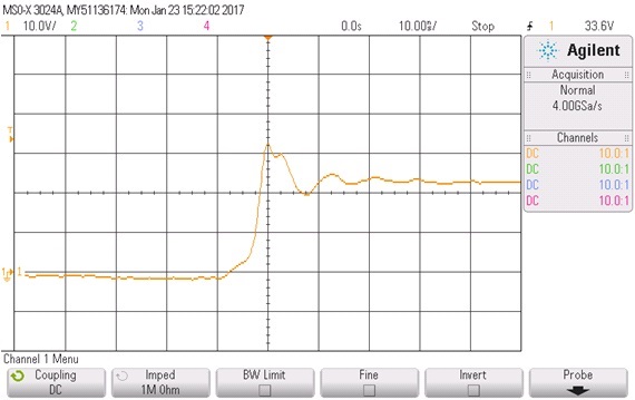
    Here are screenshoots:

    (1)switching node (10V/div , 1usec/div)

    (2)Zoom of rising edge(10V/div , 10nsec/div)

    Would you advice me on my circuit?

    Best regards

  • I'll show this to our apps team to see if they have any suggestions. What were your resistance and Qg targets?
  • So this ringing is still over the max BVDSS of the FET. This means you either have to reduce the ringing or use 40V FETs.

    Here are some app notes we have written about reducing ringing:

    www.ti.com/.../slpa010.pdf

    www.ti.com/.../slpa005.pdf
  • Dear Brett,
    Thank you for reply again.
    My resistance target is 2mOhms Max at VGS=4.5V.
    And my Qg target is 50nC Max at VGS=4.5V.

    I will try to reduce ringing according to app notes shown by you.
    BTW, is my FET in avalanche mode?

    Best regard
  • We do have a 40V device coming up, the CSD18510Q5B, that sounds like it will be very closer to your spec. 

    Typical resistance at 4.5Vgs will be around 1.3mOhm (maybe 1.6 max), and gate charge will be around 60nC, just a little bit above your target. Or the CSD18512Q5B, released two weeks ago, will be just over your resistance spec at 2.3mOhm max, but a bit under your gate charge spec. 

    It looks to me like your FET is not in avalanche mode. Some FETs have BVDSS a few volts higher than their datasheet rating as there is a bit of a distribution. But we cannot make any guarantee that the next 30V FET will behave the same. 

  • Dear Brett,
    Thank you for reply again.
    Thank you for introducing the items. There is a possibility that the specs of both FETs are acceptable.
    I want to conduct evaluation test for both FETs.
    When is the CSD18510Q5B scheduled to be released?

    Thank you for your opinion about avalanche. I understood that it is not the case that every FET is not in avalanche mode because each FET has a different BVDSS.

    Best regards
  • The CSD18510Q5B should be released by mid to late February.
  • Dear Brett,
    Thank you for your ongoing support.
    I will get the CSD18510Q5B when it is released.

    BTW, I tried some methods based on your application notes in order to reduce ringing on switching node.
    Increasing boot resistance or gate resistance was very effective in reducing ringing, while the temperature of the FET rose.
    (The RC snubber was already optimized in my circuit.)
    I will try to optimize the value of those resistances in order to find a point of compromise.

    Thank you very much