This thread has been locked.

If you have a related question, please click the "Ask a related question" button in the top right corner. The newly created question will be automatically linked to this question.

CSD97394Q4M: Buck NexFET Power stage fails over 28°C

Part Number: CSD97394Q4M
Other Parts Discussed in Thread: INA271

I am using the CSD97394Q4M in an application to drive dc cooling fans according to the temperature on the inside of a large chassis. These parts worked famously on bench trials with a varying PWM signal and Vin voltages up to 25 volts, so I desgned it into a backplane to control the speed of the fans. The trouble came when I attempted to run the fully loaded backplane in the environmental oven up to 30°C. My log showed that the CSD97394Q4M failed at 28°. Looking for answers I found on the Absolute Maximum Ratings that showed Vsw to PGND to be 30V max. With 24V on Vin, there is some overshoot to above 30V for maybe 2nS. Next I tried lowering Vin. Even with lower Vin I still get failures when the temperature is elevated.  What do you think the problem is and what can I do about this?

  • Paul, 

    I've reached out to our apps team to see if they can figure out what is going on here. If the device is going into repetitive avalanche, that could indeed be causing the device to overheat. We may need to see some waveforms.

    I should have a response for you shortly. 

  • Can you provide the operation conditions where the failure happened - load current, frequency, duty cycle, etc...?

    Also, any details you can provide regarding the failure will be helpful - was the device damaged? Was there a HS or LS short?
  • Thank you for your quick response! The frequency is 994 kHz, the duty cycle is somewhere between 0.3 and 0.45, and the load currents are around 1 to 1.5A. I will set up to test the circuit and log the temperature, the output voltage, and the load current tomorrow. I could also record waveforms on the Vsw pin if that would be helpful.
    Paul Norton
    Design Engineer
    Checksum, LLC
  • Thanks Paul, let me know and I will forward to my apps team to look at. 

  • The Excel file shows the failure occurring when the temperature reaches 28°C. What is strange is that the current seems to remain constant. The current "Iout drvr1" is being monitored using an INA271 with a 50mΩ resistor. The power supply voltage was 24 volts

    I was running a second CSD97394 with a power supply voltage of 20 volts (Vout Drvr2) and it continued to run. Did not record the current for this device. So at this point I would say that a lower input voltage seems to solve the problem. But why is that the failure happens at elevated temperature?  At 22 to 25° the part can operate for hours at 24 volts, no problem.

    For the CSD97394Q4M in a standard buck configuration what waveforms should I obtain?  

    Paul

  • Ok Paul, I have forwarded all your info to our apps team. Hopefully I'll be able to get back to you within 24hrs. By the way, I didn't see an attached excel file in that last post
  • couldn't figure out how to attach the excel file using this blog. When i clicked on the paper clip it sent me to another screen and I could not get back. When I tried to copy/paste it didn't work.

    PaulLog_CSD95394_Fail.xlsx

  • The first log was flawed because I did not have the thermo-couple right on the device. I discovered today that was the failure! Look at this data and you'll see that just when the part starts to fail there is an exponential rise in temperature.
  • Paul, 

    Sounds like you are going into thermal runaway, which may be a result of a repetitive avalanche event. Still waiting for a response from our apps. 

  • Paul,
    Could you capture wave forms of the PWM signal and VSW?
  • Hi Brett,

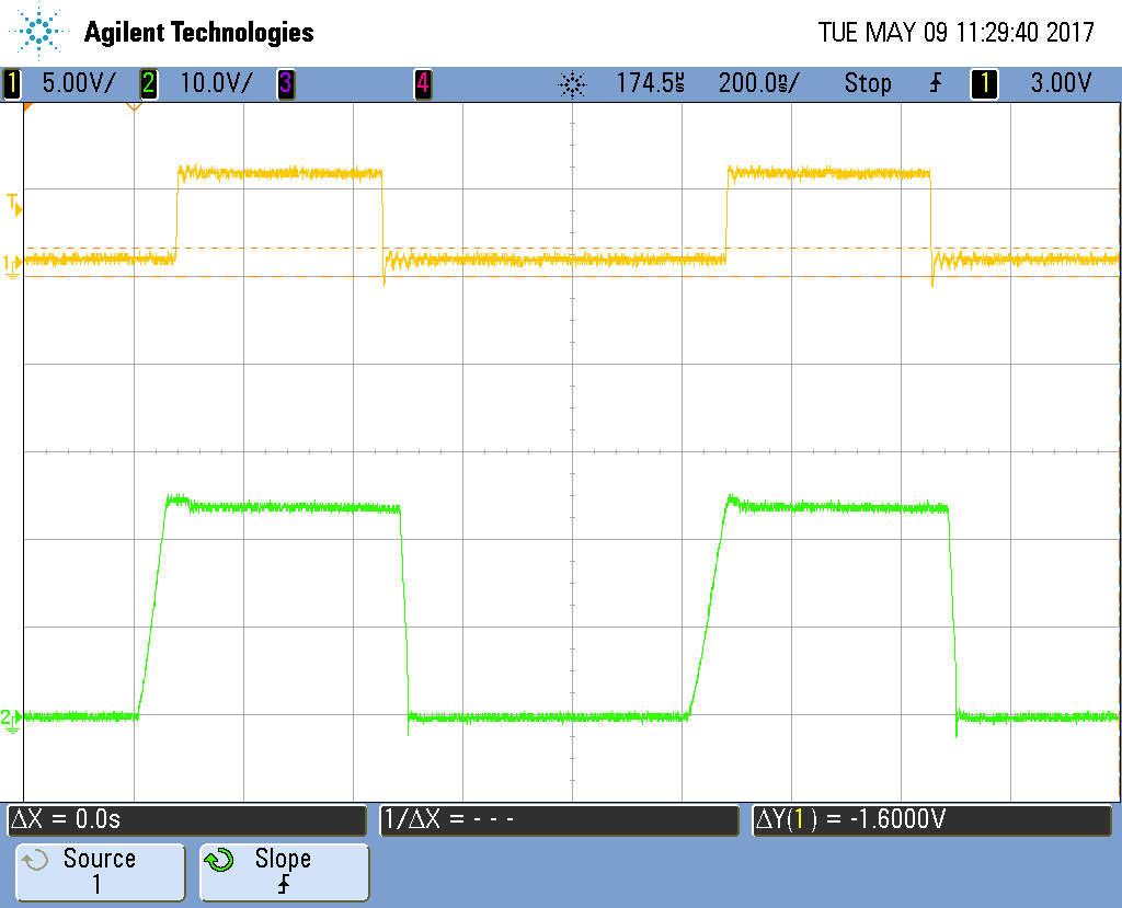
    The attached png scope_5.png shows what the waveforms looked like just as it was failing. The yellow trace is the PWM input, and the green trace is Vsw.  Nothing out of the ordinary. "scope_4.png" was captured as an irregular waveform (took many captures to finally get this, and this is with a good scope ground). The strange thing is that the Vsw goes high before the clock pulse.

    Also attached is the data log showing the exponential temperature rise when the failure was occurring.

    Thank you for looking into this.

    Paul

  • It seems with this ap, I can only send one attachment, then it won't let me send any more. My email is paul.norton@checksum.com , if you would like to communicate that way.
    Paul
  • Hmm that is strange. Can you send png.4 and png.5 to me directly at my address b-barr@ti.com?
  • Paul,
    Copied below is the response from our applications engineer:

    "For customer’ s question on #SKIP pin, here explains how #SKIP works: When #SKIP is 5V, Power Stage works on FCCM mode; while when #SKIP is 0V, DCM model is enabled. With inductor current always higher than the critical current, the driver operations are the same for both FCCM mode and DCM mode. The difference happens at currents lower than the critical current: current can go negative with FCCM mode; while for DCM mode, the driver will turn off LS FET when negative current is detected and the inductor current will stay at 0 until PWM high comes. DCM mode shouldn’t be the reason for the part failure.

    Is Picture "scope_4.png" measured with #SKIP high or low? It looks like DCM operation to me, when LS is turned off, a small negative current could cause HS body diode conduction and generate a waveform as scope_4.png.


    Could you please check with customer the following questions?

    (1) How they control PWM?
    (2) Is the control loop stable at all input voltages? Typically, the control loop bandwidth and phase margin change with VIN voltage. Please make sure the loop is stable at all VIN.
    (3) The customer mentioned that the load current is 1~1.5A, is this the steady state current? is it possible that the current is much higher in some states such as load transient?
    (4) Another possibility could be that the noise is higher with higher VIN, high noise might cause system stability issue as well. Please check if the loop is stable with high VIN, please also check if there are burst of PWM pulses which could cause high current."