This thread has been locked.

If you have a related question, please click the "Ask a related question" button in the top right corner. The newly created question will be automatically linked to this question.

LMZ13608 Cff

Other Parts Discussed in Thread: LMZ13608

Hi,

In the simplified application schematic for LMZ13608 (page 3 of the datasheet) is mentioned  capacitor Cff. What is purpose of this capacitor?


As I see most of the typical performance characteristics are given for Cff=4.7nF. What will be happen if not use this capacitor?

  • I will pass this question to the apps engineer.

  • The Cff capacitor is used to speed up the transient response of the buck regulator.

    It adds a zero to the compensation at (1/(2pi*Rfbt*Cff) that can be placed  near the crossover frequency of the converter.  The zero causes the crossover frequency to be higher and adds phase boost. 

    If too large a capacitor is used the zero is moved to low frequencies and can cause the crossover frequency to be too high and can cause the converter to be unstable.  The 4.7nF value was selected based upon the top feedback resistors in the table and using two 330uF tantalum polymer output capacitors.

    Regards,

    Marc

  • Marc, thanks for your answer.

    I understand your input about zero compensation.

    As Cff nominal is correspond to zero we should know the crossover frequency  and the pole of the feedback to place right value of the Cff.

    Unfortunately I couldn't find information about converter crossover frequency for LM13608.

    Am I correct, that pole is determined by L*Cout, 1/(2*pi*sqrt(LCout)), where L=2.2uH is integrated inductor and Cout  is output capacitance?

    Should I take something else into account?

  • Hi,

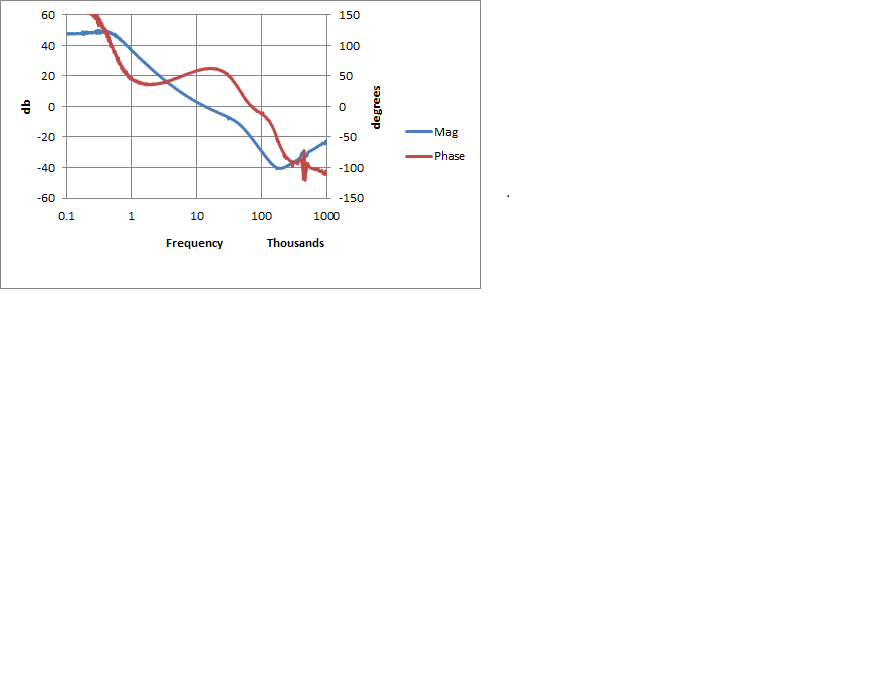
    Here is abode plot of the frequency response of the FB loop.

    The conditions are: 12Vin to 3.3vout, Iout =6A with two 220uf polymer caps that have an esr of 22mohms and no Cff capacitor. 

    Looking at the Graph, the crossover is around 12K.    Because this is current mode control the inductor pole is decoupled from the capacitor pole as long as the ratio of slope compensation to inductor downslope is close to 1.  If you look at the blue curve you can see that a little below 1Khz there is a pole.This is the output capacitor pole.  It is at 1(/2*pi*Cout*Rout)  where Rout = 3.3V/6A = .5.  This places a pole around 723 Hz.  Adjusting this pole will adjust the crossover frequency.  You will notice the phase boost at 10-20Khz.  This is due to the esr of the output capacitor which places a zero at 1/(2*pi*Cout*esr) = 16Khz.  So in this case the Cff is not necessary because the esr causes the phase boost at the appropriate frequency.  However if you were using ceramic capacitors you would want to add the Cff to provide phase boost in the area.  If you use smaller output capacitors the crossover frequency will be higher  and you would want to use a smaller Cff capacitor. 

    Regards,

    Marc

  • Marc , thanks for you explanation,

    According to your explanation the crossover frequency for LMZ13608 is dependent from output current. If we take that open loop gain is 50db than crossover frequency will be roughly 20 times higher than pole from output capacitor. For second order filter we have amplitude slope about 40dB/decade or 12dB/octave thus we will have decrease in 52dB for 20 time change in frequency. Thus in your case we need zero compensation for frequency about 14kHz.

    In your example this was provided by by ESR of the output capacitor. In other case we will have either oscillation either we should use Cff.

    But my question will be in which range open loop gain changes over temperature? I guess you give your picture for normal condition and with temperature DC gain could changes shifting as well crossover frequency.

  • I don't have numbers for this part but I have seen +-20% on error amplifier gains over temperature AND process corners in the past. This would cause the mid-band gain to increase or decrease 10db in the worst case. In the case above the low crossover would be around 5kHz and the high would be around 50Khz. You would still want to place the zero in the middle of that band to provide the most phase boost for the widest range of cases.

    Regards,
    Marc