This thread has been locked.

If you have a related question, please click the "Ask a related question" button in the top right corner. The newly created question will be automatically linked to this question.

DCR010505U - Regulator failure

Other Parts Discussed in Thread: DCR010505, DRV103

Hello,


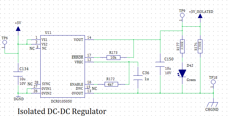
I am using a DCR010505U to provide an isolated low current supply,  the maximum load current is approximately 100mA. On some of the cards, the regulator has failed, it is hot and there is a very reduced output voltage, typically 0.5V. It appears the internal LDO has failed, as measuring the output resistance, is approximately 11R, where as a good regulator measures approximately 23k on my circuit. I have provided an output 0V power plane to the device, but it is on layer 2 of the PCB, so the device sinks any heat through the via holes. Measuring the device temperature under load was around 40°C, while other components where at about 35°C. What also I noticed was that the temperature suddenly started to runaway and I think this is the mode of failure, but cannot readily see what is causing the problem.

The sync pin is attached to a pad on the PCB, but it is an unused pin. I calculated the external capacitance and this pin to be about 0.5pF. 

Any ideas where the problem might be?

See circuit below:

  • Mike

    The circuit diagram is not viewable .

    Can you contact me directly at tguerin@ti.com with the applications schematic and your contact information  and response tot he questions ?

    Questions are:

    1. Is the DCR010505U functional when power is first applied?

    2. What is the input voltage power supply current rating ? Scope the  input voltage waveform  during power-up:

    3. Is the DCR010505 used as a +5Vout only or is it connected to (-)Voltage for +/- driver?

    4. Is there any other voltage present on Vout? Is there voltage  on the output ground  as referenced to Vin ?

    5. How much capacitance is on the Vout bus and what type capacitance?

    6. What is the input capacitance and type?

    Tom

  • Tom,

    Many thanks for the quick response, I shall contact you by email, but for completeness of this thread, here are the answers to your questions:

    1) Yes, the DCR010505U is powered from the +5V supply which features a soft start.

    2) The input 5V power supply can deliver over 4A.

    3) The DRR010505U is used as an isolated +5V supply to a CAN bus driver, a Texas Instruments DRV103.

    4) No other voltage other than +5V from the DCR010505U.

    5) All capacitors are surface mount ceramic, being X7R and X5R. The input and output capacitors are 10µF X7R and the VREC capacitor is 1µF X5R.

    The schematic is below (hopefully):

  • Tom,
    Another point I noticed, is that for some reason when I design the PCB, I placed the input capacitor on the bottom of the PCB. This means that the capacitor is connected by sort connections and via holes to the module input power pins. I have placed a 10µF capacitor on the topside of the card from GND plane to pin 1, to see if this helps.
    Mike.
  • Mike:

    Can you  send me an e-mail on this question.

    I suspect the soft start input power supply 5V bus is likely to be in current limit  during ramp-up.

    If the DCR010505 input voltage droops  below 4V, the converter may  sink excessive input current  preventing normal output voltage .

    Tom