This thread has been locked.

If you have a related question, please click the "Ask a related question" button in the top right corner. The newly created question will be automatically linked to this question.

PTB48580 noise

Other Parts Discussed in Thread: PTB48580B, PTB48580A

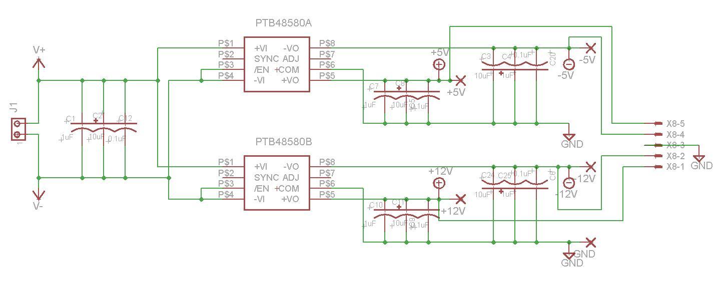
I am using the PTB48580B and PTB48580A Isolated DC/DC converters with a common 54VDC input. All of the outputs (+/-12, +/-5) have at least 200mV ripple at about 1.25MHz. I can see a spike at about 480kHz which must correspond to the switching frequency, but I do not know where this 1.25MHz ripple is coming from.  At each output, I have a 10uF tantalum cap in parallel with a 1uF tantalum and a 0.1uF ceramic chip capacitor.  I see from the datasheet that a very low ESR capacitor can cause instability, but I do not believe that any of these capacitors have low ESR. Are there any other design or layout considerations I would need to follow in order to avoid this large ripple?

From the datasheet, switching frequency synchronization is necessary when using the PTB48580 with a PTB4850x to prevent adding a beat frequency to the ripple components from the converters.  Could it be that using two PTB48580's without synchronizing them is causing this problem?  Or is synchronization only an issue when used with the PTB4850x?

Any suggestions would be greatly appreciated. Thank you in advance for your help!

  • Toth,

    Can you attach a waveform of the output voltage ripple?

    Make sure your oscilloscope is bandwidth limited to 20MHz. 

    Also, the ripple must be measured directly at the output pins with the GND of the probe as short as possible. 

  • I will paste the waveforms below.  The first is with 50ohm coupling,and the second is with 1Mohm coupling.

    I just realized that my oscilloscope was bandwidth limited to 200MHz (not 20MHz) when I took the traces.  I just looked at it with 20MHz and the lines are a bit smoother but not much different otherwise.  Let me know if you need me to post traces with the 20MHz BWL.  (It's a bit tedious to get the traces from my scope to the computer, but I'll gladly generate those plots if needed.)


    I'll also post the schematic and layout in case that might be helpful...


    Please let me know if you need any other information or if you need me to generate the 20MHz BWL plots.

    Thanks for the help!