This thread has been locked.

If you have a related question, please click the "Ask a related question" button in the top right corner. The newly created question will be automatically linked to this question.

LMZ22010: The LMZ22010 actually tests the difference between the value of the output current entering the CCM and the value of the CCM/DCM boundary calculation formula provided by the datasheet.

  • Hi,

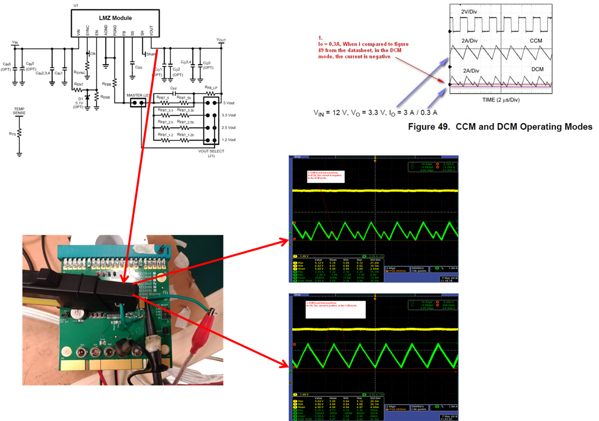
    It looks like the inductor is going negative in both picture from EV kit, is this true. When i compared to figure 49 from the datasheet, in the CCM mode, the current is all positive.

    Thanks
    -Arief
  • Hello William,

    I realize it has been some time since Arief replied to your post.
    Are you still having issues with this?

    It looks like the current goes slightly negative in the application as Arief pointed out. Depending on the zero-cross detection point and circuit delays there will be slightly negative current and some part-to-part variation. This negative current is not accounted for in the equation you mentioned.

    Cheers,
    Denislav
  • Denislav Q:
    It looks like the inductor is going negative in both picture from EV kit, is this true. When i compared to figure 49 from the datasheet, in the CCM mode, the current is all positive.

    William Ans:
    1. I to double check :
    Io= 0.3, When i compared to figure 49 from the datasheet, in the DCM mode, the current is negative, not all positive .
    2. EVM board , I to test waveform:
    Io=0.3A, The current is negative, in the DCM mode. same figure 49 DCM mode from the datasheet.
    3. EVM board , I to test waveform:
    Io=3A, The current is positive, in the CCM mode. same figure 49 CCM mode from the datasheet.
    4. The point of my question is why the current waveform enters CCM mode at 0.285A.
    Not the value calculated by Formula of DCM/CCM Boundary at 1.895A?
    5. why the current waveform after the 0.285A into the CCM mode current level will be negative again, this is where I do not know, want to consult with you at the same time.
  • Denislav Q:
     It looks like the inductor is going negative in both picture from EV kit, is this true. When i compared to figure 49 from the datasheet, in the CCM mode, the current is all positive.

    William Ans:
    1. I to double check :
    Io= 0.3, When i compared to figure 49 from the datasheet, in the DCM mode, the current is negative, not all positive .
    2. EVM board , I to test waveform:
    Io=0.3A, The current is negative, in the DCM mode.  same figure 49  DCM mode from the datasheet.
    3. EVM board , I to test waveform:
    Io=3A, The current is positive, in the CCM mode.  same figure 49  CCM mode from the datasheet.
    4. The point of my question is why the current waveform enters CCM mode at 0.285A.
    Not the value calculated by Formula of DCM/CCM Boundary at 1.895A?
    5. why the current waveform after the 0.285A into the CCM mode current level will be negative again, this is where I do not know, want to consult with you at the same time.