This thread has been locked.

If you have a related question, please click the "Ask a related question" button in the top right corner. The newly created question will be automatically linked to this question.

common grounds between positive and negative pwr supplies

Other Parts Discussed in Thread: LM5088

I am currently trying to integrate several power supplies for use on a single PCB and one of them has me concerned.  For all of the individual designs TI's webench was used as a starting point.  One of the supplies will take 5 volts and produce -3.3V.  Webench gave us an inverting buck boost topology using LM5088.  We ordered an eval board for the LM5088, and modified it to match our Webench schematic.  The circuit works as far as output voltage and current requirements.  The concern I have is that on the particular circuit, for -3.3V output, we have to swap our gnd and vout.  This poses a problem in that all of the supplies on the board will need a common gnd.  Is there any way to integrate this circuit with the others (that I am missing), or do I need a different topology all together for this supply?

Device:LM5088MH-1/NOPB

Topology: Inverting_Buck_Boost

Design: 3601389/17 LM5088MH-1/NOPB

  • Hi

    Now, you have one common ground for both positive and netagive power supplies.

    After you swap Vout and GND of negative power supply. OLD Vout node will be NEW ground. Don't swap vout and gnd on the positive power supply.

    Regards


  • If you have additional question, please draw both positive power supply and the negative power supply on one paper then post it for me.

  • Thanks for the quick response.  The issue I had, and you verified what I had hoped, was that the eval board that we are testing with was designed for +5 out.  So on the board the two grounds are connected.  By changing the circuit up and switching our references on the output side, I thought we would have issues integrating it with the other supplies.  What I did was the lift all the input caps and connect them to the Vout+(the new ground) and connect all gnds to a common point.  This will work fine for our preliminary testing.


    Again, thanks for the timely response.

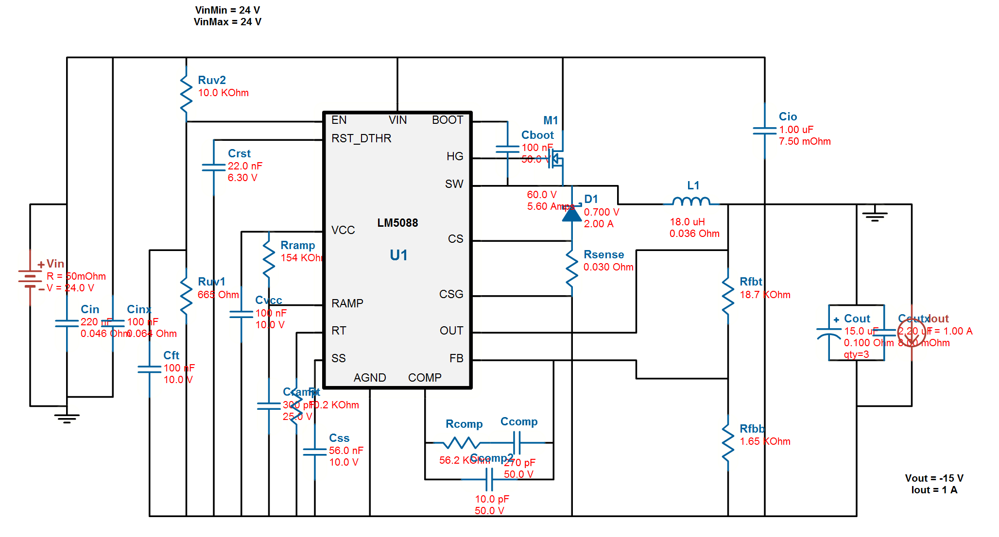
  • I have a similar situation, but using a -15V supply.  I've attached the webbench schematic similar to what I have on my board.  Problem is, I'm getting LOTS of noise (3-4V) at 300KHz.  It seems that there is an issue with the ground (Vout) of my -15V coupling noise onto the shared ground of my positive supplies.  Is there a special way to connect the LM5088 in inverted mode with positive supplies that share the same input source?