This thread has been locked.

If you have a related question, please click the "Ask a related question" button in the top right corner. The newly created question will be automatically linked to this question.

LM2621 - High startup current

Other Parts Discussed in Thread: LM2621, TPS731, LM2623

I'm working with the LM2621.

My Power Supply is a Li-Po battery with voltage range between 4.2V to 3V

With 4.2V, I can get my 5.5V perfectly. No ripple, no noise, nothing. Just Perfect!

When I power on the device with a voltage less than 3.5V, it sinks about 350mA from the source and the Vout rises to 6.3V and never gets back to 5.5V nor the current drop.

Sometimes when I power down and then power up again shortly, the voltage reaches 5.5V and the current drops. And the problem just disappear.

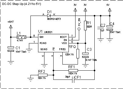
From this schematic, I've just chenged RF1 to 68K and RF2 to 20K in order to get the 5.5V Vout.

The 3V is a regulated voltage from a TPS731 LDO regulator.

Why I'm having this 350mA on startup?

Please Help.

  • Hi,

    You can try to connect EN pin to VDD and see if there is anything changed. Since the EN threshold is always lower than VDD according to the datasheet. I am not sure what happens when EN > 3V ond VDD. 

    Also if you still have issues, could you send the waveform of pin 8 and VIN and VOUT?

    Thanks

    -Arief

  • Hello Arief

    I have done some tests and I believe the problem is the EN threshold.

    My EN is tied to the ucontroller pin and the output of the pin is 3V.

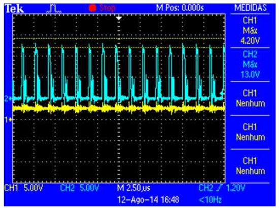
    IMAGE1:

    CH1 - Vin (2.9V)

    CH2 - PIN8
    (current  = 240mA)

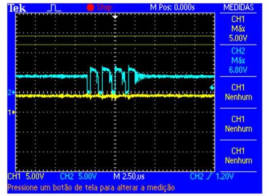
    IMAGE2:

    CH1 - Vin (4.2V)

    CH2 - PIN8
    (current = 30mA)

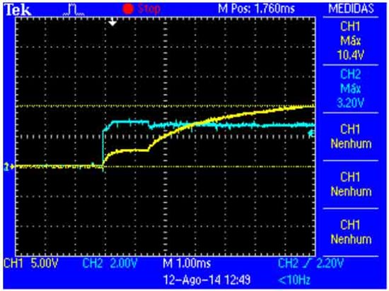
    IMAGE3:

    CH1 - Vout

    CH2 - PIN2 (EN)
    (Vin = 2.9V - current = 240mA)

    IMAGE4:

    CH1 - Vout

    CH2 - Vin (2.9V)
    (current = 240mA)

  • It looks like when you are at lower VIN, you switched more, hence the higher current that you see on the input whereas when you at 4.2V, you can see that the switching is happening less so you'll see the low value of input current.  

    So have you put the EN into its appropriate thereshold and resolve the issue?

    Thanks

    -Arief

  • Hello Arief,

    I still have issues.

    The way I tested, the EN voltage never goes below VIN ou VDD. Tying the EN to VDD, EN will never be lower than VDD also.

    So I would like to know, if I tie the EN to VDD, the problem will still occur?
    I didn't make this test yet because my PCB is mounted, so in order to test I will need to cut some tracks and wire up the pin.

    If the problem continues, I will have to sense the Vout and put some IC to switch ON/OFF the Vin when it gets lower than 3V.

    Thanks.

  • If you connect EN to VDD the problem might still occur. 
    I am just trying to meet the operating conditions in the datasheet since i saw on your EN is connected to 5V signal and i am not sure what will happen if EN > VDD.

    One way to test this is you can externally supply the EN signal but make sure is lower than the VDD at the low VIN voltage. 

    If the problem still occurs, you can have a supervisory circuit or a power on reset connected to EN to disable the part when the VIN is lower than 3V

    Thanks

    -Arief

  • Just to let you know, I've tied the EN pin to VDD, and the problem still happens.

    So that's it.

    Below 3V I can't enable the LM2629

  • Hi Alessandro,

    Can you try increasing your inductor value to 12uH? Reduce R1 to 50ohms instead of 500 and tie Enable to VDD. Let me know if this works.

    Thanks,

    Anston

  • Anston; Did you ever resolve this customer's problem? It looks like you were working
    on it pretty intently, then the thread just stops. Are you still responsible for the LM2621?

    regards, billb....
  • Bill I am glad you are still working for us!  :)

    Since we did not hear back from the customer we presume that the problem is closed; however we appreciate any help you can give, so please monitor E2E if you would like to help.

    The LM2621 has now been move to a different group; so I do not know who will be answering questions about it.

    Anston, Bill is the designer of the LM2621 and LM2623 and one of my many former bosses.

    Frank D


  • Hello,

    Sorry for not providing further information regarding this thread.

    I still have the problem, but I think I could recognize the source of the problem.

    In my board, I'm protecting the battery with a fuse. This fuse has 2.65 Ohm of cold resistance.

    The battery will supply something about 3V when almost discharged. 

    3V / 2,65ohms = 1,13A

    When full charged 4,2V / 2,65ohms = 1,58A

    I believe that this 450mA difference is the source of malfunction. The LM2621 tries to sink more current in order do stabilize the output voltage, but it never happens bacause the current is limited to 1.13A.

    I can't either increase the inductance value nor decrease the fuse resistance.

    So I empirically found the minimal voltage that LM2621 could stabilize the output voltage, and i'm shutting the IC off in firmware to prevent the malfunction from happening.

  • Hello, Frank;

    Long time no see.

    I usually Google products I was involved with a couple of times a year, but have been really busy this last

    year. The LM2621 has sentimental value for me for several reasons, and I really like to help people who

    are interested in using it. I've toyed with the notion of writing an article disclosing it's secrets & quirks, but

    I'm not sure there's enough interest to warrant it.

    This user's circuit has a number of errors, but the waveforms help zero in on the cause of the startup issue

    The enable pin glitch is a false lead; only its magnitude is significant. Vout doesn't begin to rise above Vin

    until En is stable. The reason for the poor behavior is that the bangap reference isn't sending the signal to the

    comparator needed to enable the voltage loop; the reference sends this signal only when it has enough head

    room to be operational.

    Whatever is happening with the switch pin low (nfet on), whether the current is still ratcheting up or it's

    in current limit, it's seen that, when the switch turns off, the drain voltage is clamped only by the nfet's

    esd zener. That's where all the power is going. Vout rises, in fact, over ten volts; clearly the comparator

    is not involved in the process.  Until the comparator is enabled, the driver will simply run at ~70% duty

    cycle as long as there is > 1.1V (hvpmos vt) on Vdd and en. This architecture allows the part to bootstrap

    from Vdd < 2.5V, the headroom required by the reference over temp. Image 3 shows en (and thus Vdd)

    settling to ~ 2.0V, +/- a fair amount of noise. This might be sufficient headroom at 125C, but is definitely

    not enough at room temp, especially with a power device driver hanging off the same linear supply.

    Additionally, the power nfet's gate drive is not well served by connecting it to a 3V rail; this will kill the

    efficiency. Boot, Vdd, and En should all be connected to Vout for this application. They are all, in fact,

    fine operationally up to 10V; they may leak 2uA instead of 1uA at hot, largely due to the ~14.2V zener

    esd protection. Ten volts is a good limit because the large BURLYR/ISO diodes can get a little leaky

    above 10V, even at relatively low temps.

    Moral of the story - Application Notes are your friend; there are reasons schematics are provided.

    I hope these observations are helpful.

    regards, billb....

  • Hello Bill,

    Sorry for my late reply.

    I haven't been working in this project for some time, but now i'm back on it.

    I'm really glad to know that i'm receiving advises from the IC designer.

    I've changed the circuit to be compliant to what you wrote.

    Now BOOT and VDD are connected to Vout, but EN is connected to a 3.3V GPIO pin from my microcontroller.

    The LM2621 is providing 5V to a circuit that sinks about 150mA when active and 200uA while sleeping.

    I want to cut the 5V in order to save this 200uA and remain with just the LM2621 shutdown current, that is 2.5uA MAX.

    That's the reason I'm controlling the EN pin with the uC and not tying to Vout.

    I've tested this configuration and I could see an improvement in the overall performance. The problem I once had doesn't exist anymore.

    Can you please tell me if you see any problems in the circuit below?

    The label says 4.2V to 5V, but it is actually a 4.2V to 5.5V.

    I would love to hear about LM2621 secrets & quirks. If you ever release this article, please let me know.

    I'm now trying to reduce the output ripple when Vin is about 3V and the current sunk by the 5V circuit is about 150mA.

    Thanks for your help.