This thread has been locked.

If you have a related question, please click the "Ask a related question" button in the top right corner. The newly created question will be automatically linked to this question.

LM43603 Power Regulator Problem

Other Parts Discussed in Thread: LM43603

Hi,

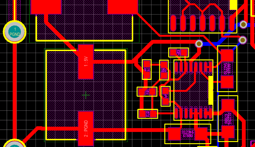
I'm attempting to manufacture 29-31V to 5V @ 0.5A power regulator using the LM43603 synchronous step-down voltage converter. I designed the circuit around the WEBENCH simulation, verified by the design equations, and constructed a PCB board where the power regulator is being used as part of a larger transmitter circuit. The schematic and PCB layout are shown below:

Due to strict size constraints, there wasn't space on the PCB to use the pad, but the ground is connected and there aren't any short-circuits. The resistor connected to RT was left open circuit to set default frequency, but a footprint was added to give the option to change. However, when testing out the manufactured board, I received the following output:

I've checked the connections and I've attempted all obvious solutions. The regulator does not appear to be switching. I would really appreciate any assistance with this matter.

Thanks in advance,

Chris

  • Unfortunately, you can not omit the DAP connection.  It is required  for proper electrical operation as well as thermal.  Also, some of you power traces, such as SW are too narrow.  I would suggest that you copy the layout found in the data sheet as a starting point; especially the power and ground connections.  The guidelines given in the data sheet are important to achieve a good working design.  The user guide for this device also shows the layer stack-up for our evaluation board.  These documents can be found on the product folder for this device.  If you like I can send you an EVM that you can use as a starting point and check out your design on a clean board.