This thread has been locked.

If you have a related question, please click the "Ask a related question" button in the top right corner. The newly created question will be automatically linked to this question.

LM2678 Lab Power Supply Design

Other Parts Discussed in Thread: LM2678, LM22678

I am designing a power supply for my personal use and basing it off the LM2678.  I plan to have it take about 36-40V input and 2-30V output with a max current of 3-4A. Right now I have a basic schematic in mind (not quite finished, but will post when I am), but I have a few questions. 

First, is it possible to control the output voltage with a DAC, and if so, what would be the best way to go about doing that? 

Also, I would like to implement a current limiting circuit into my design, but I am not sure how to integrate it with the rest of the circuit. No fancy constant current or anything, just a limiting circuit. I am also planning to design a voltage-division based arduino-powered volt and ammeter, so if possible I would like to find a way to get all of this working together.

One final thing, I have seen a PDF on TI's website explaining how to wire up a simple switcher non-synchronous buck converter into an inverting buck/boost converter. Is it possible to do that with the LM2678 to create a negative Vout, and are there any pitfalls I should avoid when trying it? Also, if it is possible, I would like to include all the previous features into the negative rail as well.

Thanks,

Jonathan

  • Your output voltage range seems quite wide for a 36V input.  I would look at that aspect of the design first.  You might want to look at a device like the LM22678; the data sheet has equations that will help you determine the minimum and maximum output voltages that are possible.  To control the output voltage with at DAC, one way is to connect the DAC output to the bottom of the lower FB resistor.  The external current limit is more tricky, unless you use a linear reg as a current limiter, but that will dissipate a lot of power.

  • Ok, I'll look into that. Is it possible to use this for a wide range? I am intending this supply to be used as a lab bench supply, so the wider the range, the better. I don't expect it to be optimal for all voltages, but as long as it can work with <1% ripple I'm fine with it, and I can increase the input voltage to 40V if it helps. 

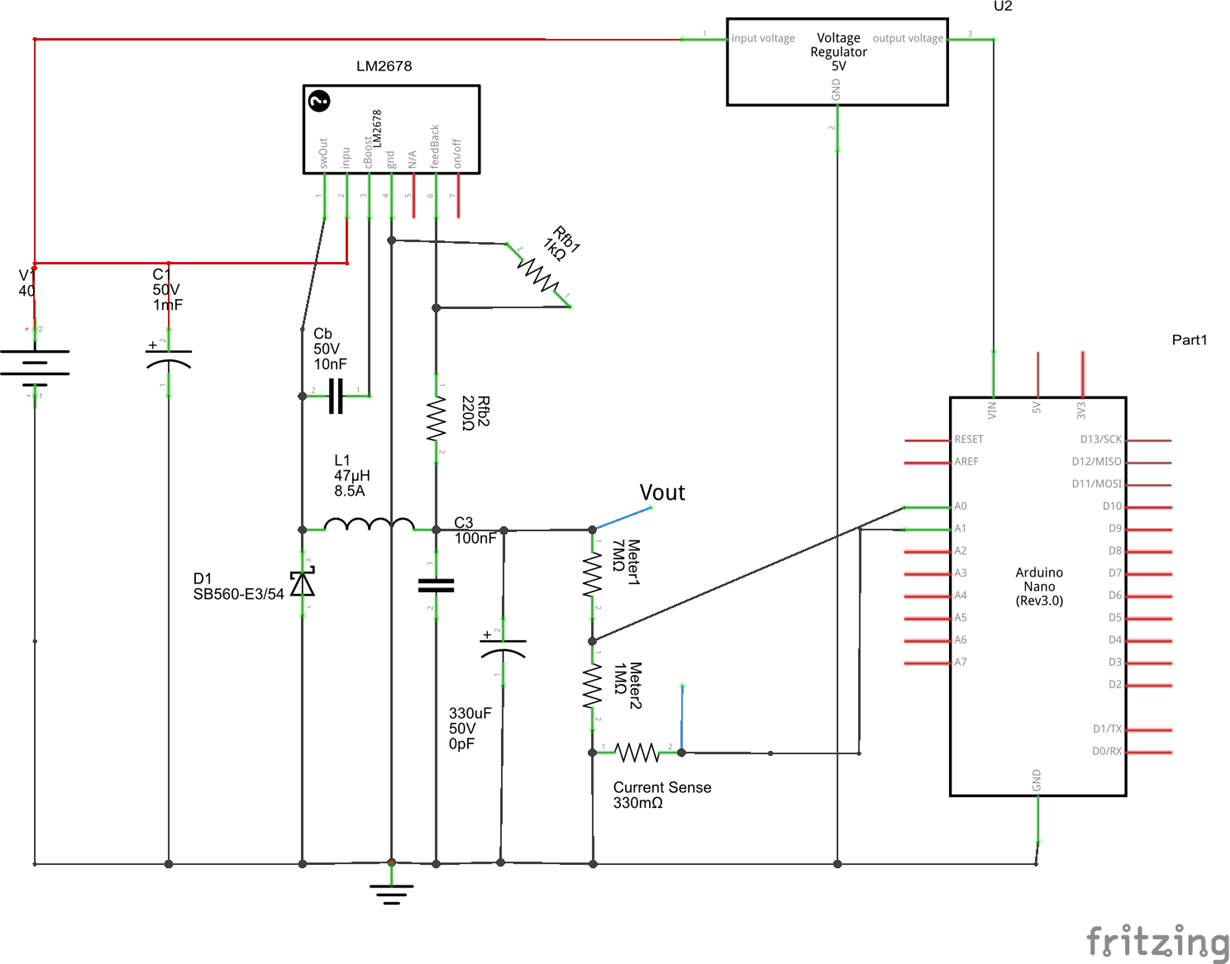
    EDIT: here is my current schematic, its a little messy, but It's basically what I have so far. The 5v regulator is just generic and I'll figure out how to get that working, shouldn't be too much trouble.

    I might go with a 39uH inductor, as that seems to be closer to the values that I calculated (calculated 40uH at 15V and 30uH at 5V&25V for the LM2678's 260kHz) and not as far off at the endpoint voltages (since this is a one-off project, it's not too hard to use non-standard sizes).

    Also, the 220 ohm resistor is just a placeholder, I'm not finished deciding on how I want to adjust the output yet.

  • The schematic looks OK.  However, I think you will need more input capacitor; check the data sheet again.

    Also, the most important thing with any switcher is the layout.  Please look at the example in the LM22678 data sheet and try to follow that.

    Also, look at application note SNVA054 from TI.


  • Yes, Im going to use a few input caps along with a .1uf ceramic with the input and output caps. I have seen a couple example layouts, and I'm going to work on that next. Thanks for the help, I'll post the PCB schematic in a couple days.

    EDIT:

    I have one more question about the capacitors. If I go higher than the reccommended capacitance value, how does that affect the circuit? Also, I read that the allowable ripple current for the capacitors should be at least 1/2 the max expected current, and the datasheet recommended using multiple caps. How important is this? If I add too many more caps, it will become more difficult to keep the traces as short as possible.

  • Hello

    I was looking over your design (Looks Good), and what the others posted,, They all gave you Excellent advice.

    I have a suggestion,,, how about using your dac to control a digital potentiometer at your ground to feedback resister. you would need to reconfigure your Voltage Divider circuit.

    For your DAC I was thinking something like the C2000 Launch Pad and that can double as a digital read out.
    It's Just a Thought. But I hope it helps.
    Jeff
  • Ok, it's been a while, but here is my (mostly) final schematic. The AD chips are 20K Ohm digital potentiometers hooked up to the arduino via I2C, the 5V regulator is actually a switching mode, so it can handle up to 40V, and the bottom circuit is the negative with an op-amp inverter with gain of 1 so the arduino can read the voltage of the divider. I have breadboarded the negative supply, and the AD2678 is getting really hot and only going from -6-0V, and I'm not sure why. Here is the current schematic:

  • How much load on the negative supply ??

    What kind of layout/PCB do you have??

    Try to scope the switch and vout to see if it is oscillating.


  • I was testing it at no load, not even the sensing resistors. I was just running it on a solderless breadboard to test its functionality, with the same type set up, no load i was able to go from 0-Vin on the positive supply. Ill check the switch to see what's happening
  • I think that some, if not all of the trouble is using the solderless board.  You may have to "bite-the-bullet" and try it on a PCB.


  • OK, ill do that. I just started working on the pcb, so i will post that here when its finished.
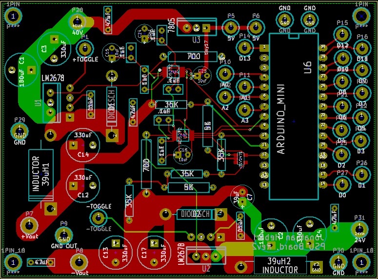
  • OK, here is my current PCB. The top half is positive, the bottom half is a negative buck-boost. Do you see any major issues with it? This is only like my second PCB ever, so any tips would be appreciated.