This thread has been locked.

If you have a related question, please click the "Ask a related question" button in the top right corner. The newly created question will be automatically linked to this question.

Bode plot for LMZ31707

Other Parts Discussed in Thread: LMZ31707

Dear Sirs,

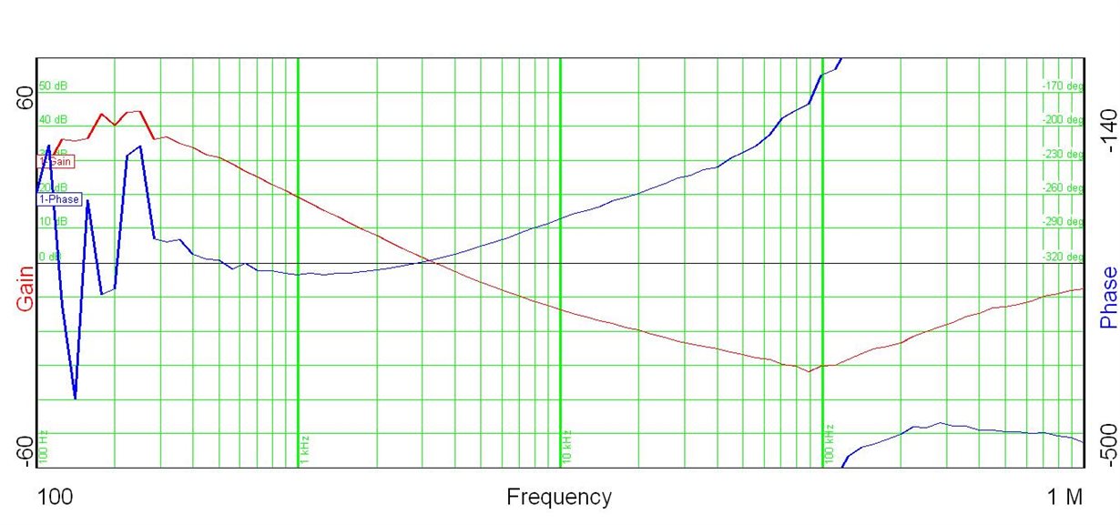
  We are trying to measure bode plot on LMZ31707 but the test result is fail.

We put 20 ohm between sense+ pin to Vout pin & inject noise to measure it. 

Out test equipment is Venable 3120.

Would you have any suggestion about the test method? Or do you suggest to measure bode plot for LMZ31707?

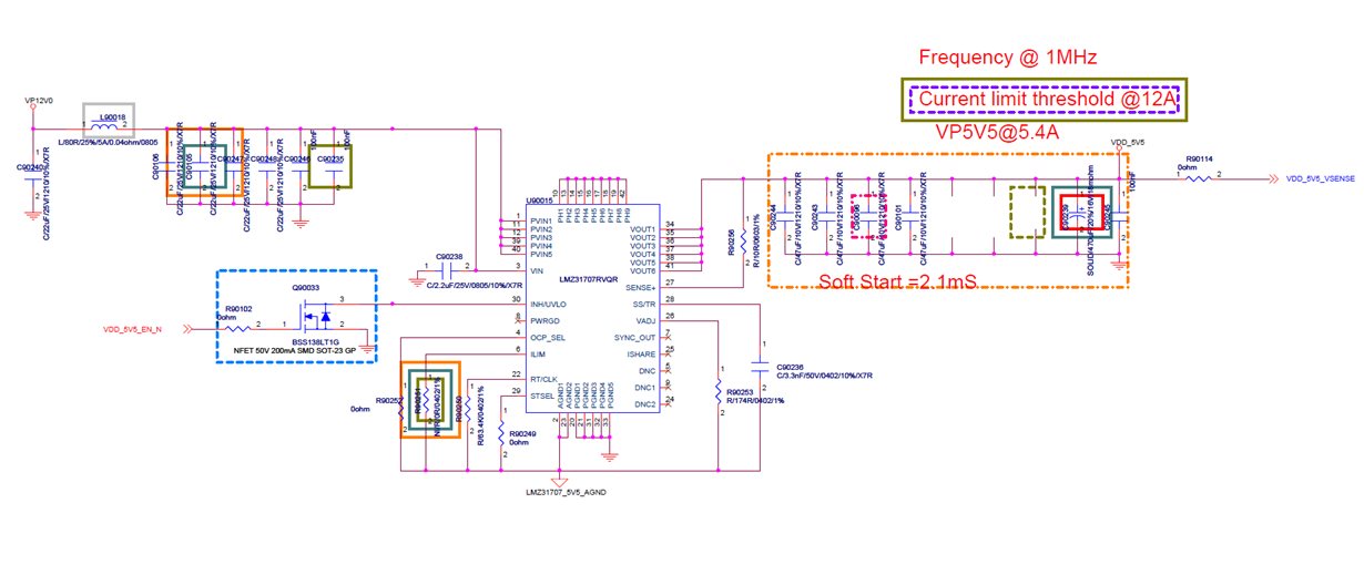
Attached schematic & test result, FYR.

Thanks.

  • Hi ShihChin,

    The simplese way to measure the bode plot would be to insert a 49.9ohm resistor between Vout (CH B) and SENSE+ (CH A), and make measurements of CHB/CHA.  You may need to adjust the injestion signal's amplitude and frequency.  I would also suggest that you put 0dB and 0 degree phase on the same center line in the plot.

    Please let us know should you have any further question.

    Thanks,

    Hung

  • Hi Hung,

      We already use your method to measure it but result was attached on last mail.

    Do you have any suggestion for the test result?

    You can see the phase line is going to up but not going down.

    Thanks.

  • Hi ShihChin,

    Can you please show me how you connected the measurements in details?  Meanwhile, please let me know the operating conditions, including Vin, Vout, and Iout.  Furthermore, what the board under tests used exactly same component values you had shown in the schematics? 

    You can email me all the information at chung@ti.com

    Thanks,

    Hung