This thread has been locked.

If you have a related question, please click the "Ask a related question" button in the top right corner. The newly created question will be automatically linked to this question.

LMR22007 replacement wide input small footprint buck.

Other Parts Discussed in Thread: LMR22007, TPS62160, TPS62170, TPS62125, TPS82674, LMZ21700

I was working on a design using LMR22007 for a few reasons

1. Size the XBGA very small for my tiny board.

2. Wide input. External power is 12v in my case.

I just noticed today in looking over sourcing the part that it is EOL or soon to be EOL but I can not find any mention of its replacement or anything on TI offerings that comes close to these critical features.

Anyone know what would be a good replacement for building a small buck regulator for 3v and I also need 1.2v but will probably use a linear regulator for that if I can not find a good "dual" solution. I am currently fitting the circuit into 5mm x 6mm space.

Thanks for any help.

Re

 Sean M

  • Sean,
    Let me look for this and I will get back to you soon.
    Regards,
    Akshay
  • Do I understand that you have 12Vin and need 3V and 1.2V out? How much current is needed on each of those rails?

  • Yes it is a wide input from say a battery or powered by USB at 5v. Could be as low as 5v and as high as 14 but the norm would be ~12v

    I need 3v3 and 1v2 to power a Spartan 6 XC6SLX4 with minimal current and only a few io pins with 25-50% cell usage.

    I estimate less than 250mA and likely only as much as 100mA in my use case but I would like room to future proof this design if I need more power later.

    I would like to limit it to ~450mA to power via USB.

    I would prefer linear regulators to keep noise down but with inrush and ramp up time as well as the problems I would see with the large voltage difference from input to load would produce a lot of heat I feel I am best off using a buck regulator.

    I am still considering a buck for 12->3.3 then a linear regulator for 3.3 -> 1.2.

    From what I can tell from the datasheet on the Spartan 6 I "should" have minimal issues with power up sequences as it has some minimal internal power checking before the chip enables itself and as long as my 3v3 is up first by a small amount the program flash for the FPGA "should" be ready to handle any requests as soon as the 1.2 comes online and the FPGA starts reading.

    Thanks for your input thoughts. Way to much data......... not enough time.

    Sean M

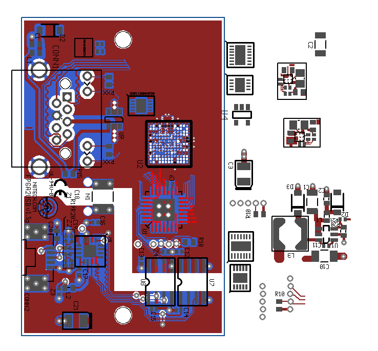
    A few power designs off to the right need to fit inside the layout on the left.

  • Thanks for the details.

    I would recommend the TPS62125 for the 3.3V rail. It has the TPS62170 and TPS62160 as higher current pin to pin alternatives.

    Then, the TPS82674/5/7 would be the smallest way to get from 3.3V to 1.2V. The PG output of the TPS62125 could hold the EN pin of the TPS82674 low to get sequencing if you want.
  • All good inputs. As I've been told the TPS62179 is a replacement for the LMR22007. 
    As another option I would also like to suggest using LMZ21700/01 for your entire requirement. These are the new nano modules and part of the SIMPLE SWITCHER family that are real tiny and can do a complete solution in 36mm2 with a very low BOM count and features such as PGOOD and external SOFTSTART. Here is the datasheet: 

    Regards,
    Akshay

  • Akshay.

    Thanks for this info I had been looking and not seen this one yet. It looks very small and simple to use.

    Does A PCB layout pattern for 2 layers?

    The TPS62179 is well documented and small but still much larger than the LMR22007 so I am still considering it but would prefer to use the smaller module to save room on my PCB for future components.

    Re
    Sean M
  • Right. The nano modules are real space savers and featured on WEBENCH. The PCB layout can be done on two layers too. The EVM although, would have been done using 4 layers. The EMI results shown in the user guide are for the 4 layer PCB. But if it is done well, the 2 layer PCB shouldn't be too far off from the 4 layer in EMI results. Just try and adhere to the layout guidelines in the datasheet. It is fairly easy to do so because of the compactness.

    Regards,
    Akshay
  • Sean,

    Here is another presentation to further influence your decision.

    Regards,

    Akshay

    LMZ21701_PCB_Layout_Options.pdf