This thread has been locked.

If you have a related question, please click the "Ask a related question" button in the top right corner. The newly created question will be automatically linked to this question.

LMR14203 load step response

Other Parts Discussed in Thread: LMR14203

Hello,

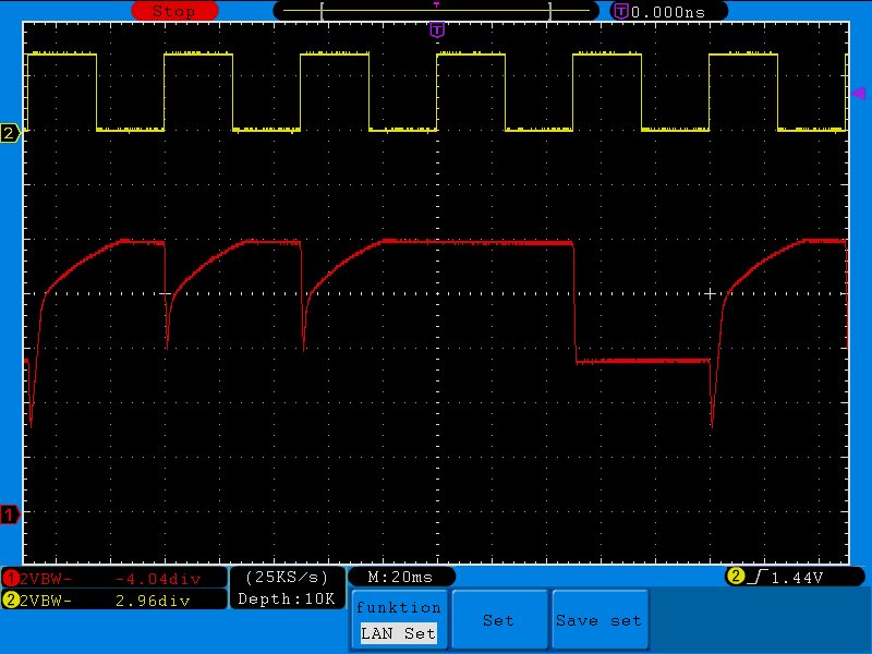
I am using the LMR14203 to charge a buffer of an LED flasher. The buffer is 20x 47uF/16V MLCC capacitor. The supply voltage is 24V and the buffer voltage is 9V. During the LED flash the buffer voltage will drop 4V. The LMR14203 will recharge the buffer in about 20ms. Basically this works ok, but I did find a problem.

The image below shows the pulse trigger (yellow) vs the buffer voltage (red). The trigger will pulse the LED 4 times in a row and then skip one. This is intended behaviour.

You see when the pulse is skipped the buffer voltage will remain the same after the trigger. Then however, the interesting part starts. The first pulse after the ignored one will draw 4V out of the buffer. Contrary to what I would expect the LMR14203 does not start to recharge the buffer at this moment. Only after the 2nd pulse, if the buffer voltage drops even lower, the recharge starts. After that, each pulse gives the response I would expect.

My guess is that the sudden voltage drop activates the short circuit protection. But if this is the case I would expect this to happen at each pulse.

Is there a way I can improve this behaviour?

  • It would be helpful to see your schematic.  If you do not want to post it on the forum you can send it to us on simpleswitcherapps@ti.com.

    I think you are probably correct about the current limit; it may be folding back.  As an experiment you can try lowering the input voltage and see if it helps.

    FD

  • Yesterday I did some more testing.

    I think there is definitely something wrong with this setup. I decreased the Vin to 12V. The input voltage makes no difference. Then I increased the Vin back to 24V. At this point the chip started smoking. This is odd. The LMR14203 should be able to handle 42V. My supply is incapable of supplying more than 32V.

    I replaced the chip, but eventually the new LMR14203 broke down again.

    One of my theories is that the overload is just too much for the LMR14203. During the pulse the LED draws 2A. I assumed that the LMR14203 would just limit the current to 0.3A, but it seems that it will just try to supply the current until it dies. The datasheet mentions a short circuit protection, but it is not mentioned how this would be implemented.

    Another thing I though of, is that maybe the sudden voltage drop when the LED pulses could cause problems with the gate drive circuitry. I cannot imagine exactly how, but I ran out of more plausible ideas. I was looking for specifications for the maximum voltage over Cboot, but I did not find any.

    Do you have any other ideas?

  • The device should limit the current to the current limit  value of about ~500mA unless the inductor saturates.  Make sure that you inductor is rated for at least the current limit.  If you can check the inductor current with a current probe to see what is going on.  Also, if you can send you schematic and a pdf of the layout to the email above, we will look to see if there is anything strange. 

    FD