Hi,
I'm fairly new to this and just need a bit of help.
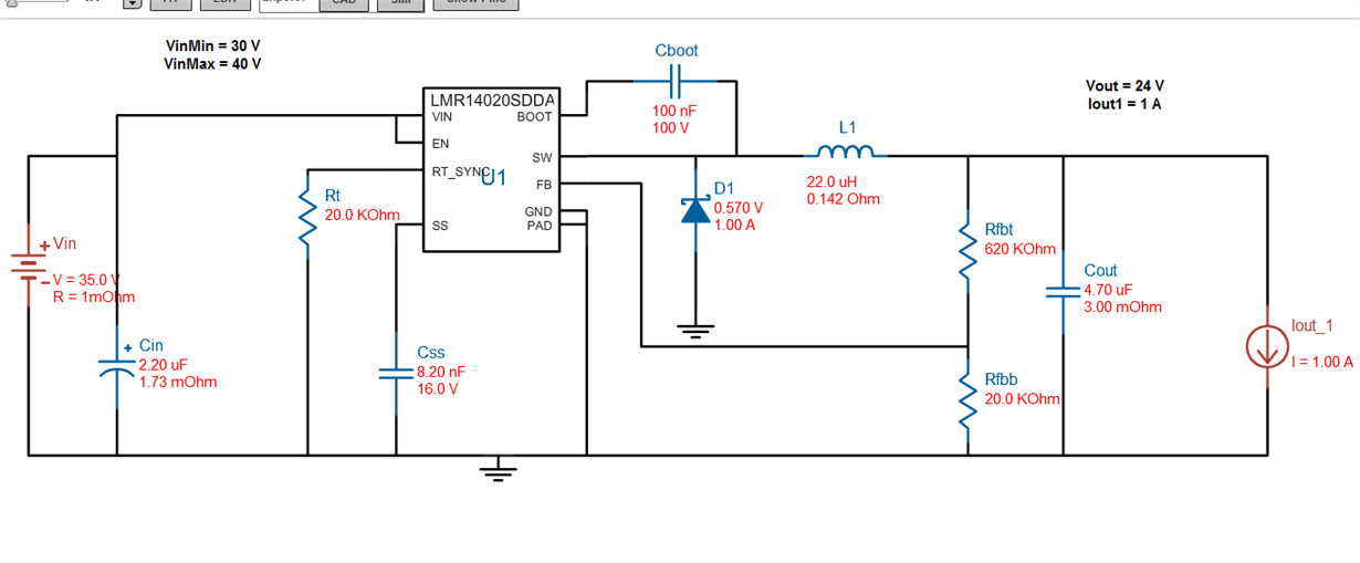
I bread boarded circuit as described by TI's web bench with substitutions from surface mount to through hole components w/ similar / same values.
I got an output of 25VDC from a 36VDC input with the saw-tooth waveform as expected which I am fairly happy with.
However, when I hook a load directly across the output terminals, this shorts the chip immediately. For example, a small brushed DC motor (not the brightest idea) and the chip shorted and drew all available current.
Then I replaced the chip, turned power off, hooked up a 24VDC low amperage photobeam (<20mA) and powered the circuit. The photobeam lit and drew the correct amount of current. I disconnected the photobeam and reconnected it. This killed the chip again.
So it seems that connecting something across the + and - while powered is my problem. This is most likely a trivial problem but I am at a loss.
Any advice is appreciated.
Thank you,
Mat


