This thread has been locked.

If you have a related question, please click the "Ask a related question" button in the top right corner. The newly created question will be automatically linked to this question.

LMZ10504: Enable Pin Coupling noise from Regulator

Part Number: LMZ10504

The Design is implementing a LMZ10504TZX-ADJ Regulator. Vin is 5V and the Enable pin is pulled up to Vin with 7.5K ohm resistor.

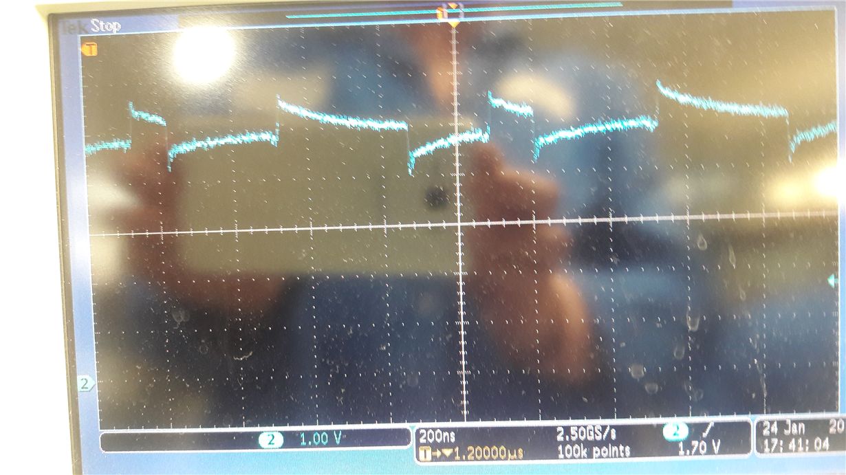
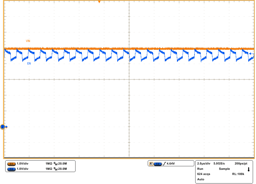
When observing the Enable pin, it appears to be carrying a switching signal that dips -750mV and rises 500mV from the Vin level. Vin is at 5V and is clean. Why would the enable pin be tracking some  internal switching signal? Please see the Enable pin wave form below.


  • Hello Eric,

    Is this measurement taken on the evaluation board?
    If not, could you share your schematic and layout if possible?

    It looks like the signal + the ripple is still much greater than the 1.8V EN High threshold, but it is a good question.
    I am hoping to check this on an evaluation board.

    Cheers,
    Denislav
  • Hi Denislav,


    This is not on the evaluation board. This is on our board design. This enable signal ripple follows the current peaks and valleys of the current on the output - used a current meter to display on scope. There is also a 100mV switching noise on the input (+5V)  which I am trying to lower. It appears that the the enable pin is not buffered and the current changes inside the regulator is coupled onto the enable pin. The swing of the enable pin noise is a near a magnitude greater than the Vin ripple. Since the Enable is pulled up to Vin, it is understandable that any ripple on vin for be on the enable signal, but I would like to understand why the enable signal swing is following the current changes . Please see  schematic below.

  • Hello Eric, 

    I see similar kind of switch node coupling on the evaluation board as well. 

    I suspect this may be due to capacitive coupling from the SW node to the EN line inside the module package - perhaps due to the close proximity of all components inside the part. 

    I think this AC coupling should not affect the operation of the module (e.g. turning off the part) because:

    1. The signal is pulled up to VIN and is far away from the enable threshold.

    2. The AC signal frequency is at the switching frequency so it is much faster to what the EN can respond to.

    Let me know if you have a concern about the application. 

    Cheers, 

    Denislav