This thread has been locked.

If you have a related question, please click the "Ask a related question" button in the top right corner. The newly created question will be automatically linked to this question.

TPS386000 - Irregular behavior

Other Parts Discussed in Thread: TPS386000

Hello,

My customer have some questions about TPS386000.

[Their schematic]

Their schematic is as follows.

[Behavior]

Please see the following.

  1. SENSE1 & SENSE2 & SENSE3 & SENSE4L > 0.5V > VITN+VHYSN → Reset released after delay → Looks Good.
  2. After that SENSE2 goes to 0V → Reset asserted → Looks Good.
  3. After that SENSE2 goes to greater than 0.5V. → Reset still asserted. → Looks Bad. This is irregular behavior.

[Q1]

Is it possible the resistors for CTn are pulled up together?

[Q2]

Do you have any problems for their schematic ?

Please let me know.

Best Regards,

Hiroshi Katsunaga

  • Hi Hiroshi,

    I do not see any issues with your schematic at this time. I assume that when you are stating 0.5V that you are directly on the pin. As this is a quad SVS and you have tied all of the outputs together, is it possible that one of your other inputs has dropped below the threshold?

    Very Respectfully,
    Ryan
  • Hi Ryan,

    Thank you for your fast response.

    [Your Comment]

    I do not see any issues with your schematic at this time.

    [My Comment]

    I think so.

    [Your Comment]

    I assume that when you are stating 0.5V that you are directly on the pin.

    [My Comment]

    Yes, Your understanding is correct.

    They are directly on the SENSEn pins.

    [Your Comment]

    As this is a quad SVS and you have tied all of the outputs together, is it possible that one of your other inputs has dropped below the threshold?

    [My Comment]

    Their other inputs did not drop below the threshold.

    [Additional Information from the customer]

    This behavior was observed in two devices of two devices (ALL) in SENSE1, SENSE2 and SENSE3.

    The voltage of CTn pins were 0V.

    [Additional Information from me]

    I made a similar experiment in TPS386000EVM (HPA428-001).

    However, the behavior has not been reproduced.


    A pull-up resistor for CTn that was pulled up together is a concern in their schematic.

    Do you have any good idea to solve this problem ?

    Best Regards,

    Hiroshi Katsunaga

  • Hi Hiroshi,

    We also were unable to reproduce this on an EVM. After modifying the EVM to match their schematic, /RESET was high when all the sense signals were above the threshold and low when any combination of sense signals were below their respective threshold. Is there any further information that you could provide about the customer's setup?

    Very Respectfully,
    Ryan
  • Hi Ryan,

    Thank you for your many support.

    Their setups are as follows.

    They were tested by contacting with the GND node and the SENSE2 node to connect the wire between the RS2H and the RS2L.

    They used passive probe for the oscilloscope waveform.

    I attached the waveforms.

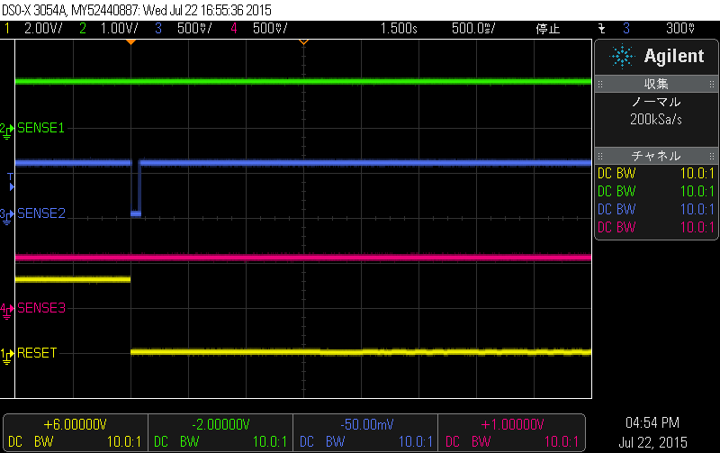
    <Waveform1>

    SENSE1(Green)

    SENSE2(Blue)

    SENSE3(Red)

    RESET(Yellow)

    ※ The RESET asserted when the SENSE2 was a transition from SENSE2>VITN to 0V.

    ※ The RESET did not released when the SENSE2 was a trainsition from 0V to SENSE2>VITN.

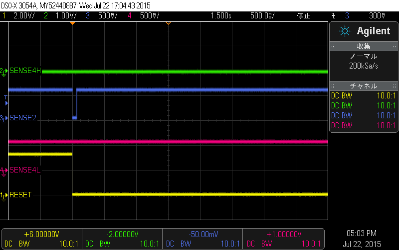
    <Waveform2>

    SENSE4H(Green)

    SENSE2(Blue)

    SENSE4L(Red)

    RESET(Yellow)

    ※ The RESET asserted when the SENSE2 was a transition from SENSE2>VITN to 0V.

    ※ The RESET did not released when the SENSE2 was a trainsition from 0V to SENSE2>VITN.

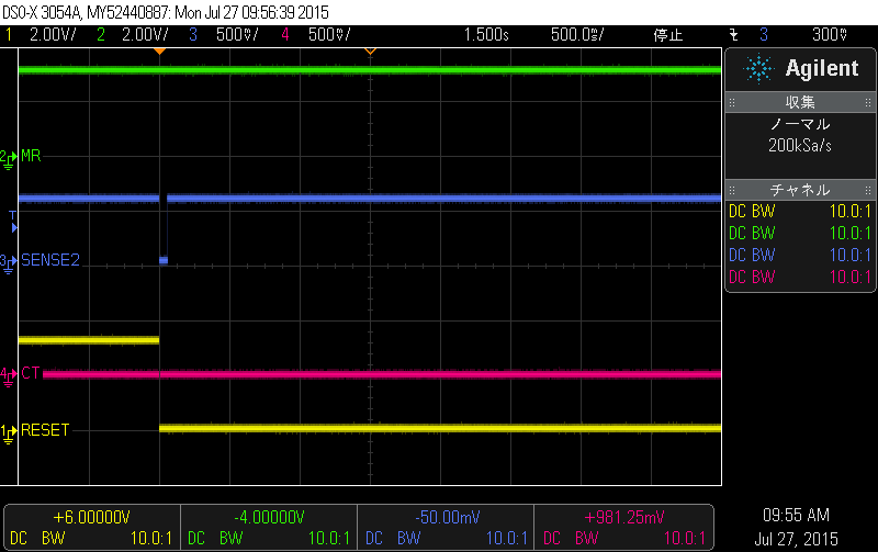
    <Waveform3>

    MR(Green)

    SENSE2(Blue)

    CT(Red)

    RESET(Yellow)

    ※ The RESET asserted when the SENSE2 was a transition from SENSE2>VITN to 0V.

    ※ The RESET did not released when the SENSE2 was a trainsition from 0V to SENSE2>VITN.

    ※ CT was 0V. (It was 5V when I checked in EVM.)

    How do you think about it ?

    Please give me some comments.

    Best Regards,

    Hiroshi Katsunaga

  • Hi Hiroshi,

    Thank you for the additional information. Does this type of event only occur if a transition is made on SENSE2 or does it also occur on any of the senses?

    Also, does removing the 100k resistor on the CT pins have an affect?

    Very Respectfully,
    Ryan
  • Hi Ryan,

    Thank you for your support.

    They tried some.

    I show them as follows.

    • Removing the 100k resistor on the CT pins (CT pins are connected together) -> The result did not change.
    • Cut the patterns connected the CT pins together and populated the pull-up resistors in each. -> A good result was provided.

    The problem seems to be to connect CT pins together.


    How do you think about it ?

    Please give me some comments.

    Best Regards,

    Hiroshi Katsunaga


  • Hi Hiroshi,

    Thank you for the additional information. We have done some more bench tests ourselves. We agree with your conclusion that the issue is the CT pins being tied together. After a channel completes the timing delay, CT is discharged internally. This discharge on the other three channels is preventing the fourth channel to properly charge CT. As a result, the timing delay does not complete and /RESET remains low.

    We are noting in the datasheet that the CT pins should not be tied together in the next revision of the datasheet.

    Very Respectfully,
    Ryan
  • Hi Ryan,

    Thank you for your fast response.
    I understood your comment.
    We became completely clear !

    I am grateful for you dedicated support !

    Best Regards,
    Hiroshi Katsunaga