This thread has been locked.

If you have a related question, please click the "Ask a related question" button in the top right corner. The newly created question will be automatically linked to this question.

The risk of power leak of the TPS3813K33

Other Parts Discussed in Thread: TPS3813

Hola,

Our customer have a question about the risk of power leak of the TPS3813K33 as below:

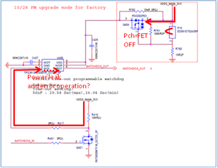
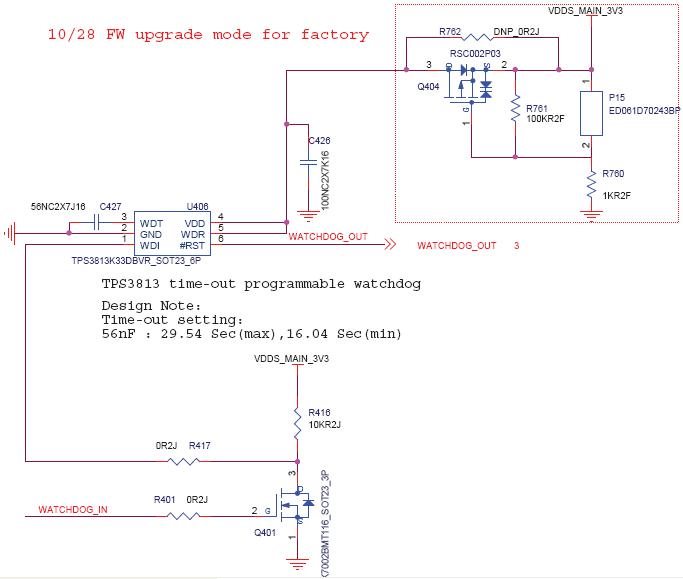
The disabling circuit of the watchdog stops to a supply power to watchdog IC(U406). But doesn't it have a risk of error operation?

Because it has a chance of power leak from WDI to RST block. Please confirm this risk to TI.


  • HI Jacky,

    If you can guarantee WATCHDOG_IN is high before VDDS_MAIN_3V3 comes up, the WDI pin will always see 0V. The watchdog will not start until it sees a rising edge on the WDI pin. If you are concerned about some back-drive in a power down state where WATCHDOG_IN is undefined and there is some leakage on VDDS_MAIN_3V3, then I would recommend putting a weak pull-down resistor on WDI to GND to help keep it from floating up. Something around 100K or larger.

    I hope this answers your question.
  • Hola John,
    Thank you very so much.
  • Hi Jacky,

    I apologize for the confusion, we had a application note erroneously attached to the product folders of TPS3813 that implied that the watchdog could be disabled. This app note does not apply to the TPS3813 family.

    The upper boundary of the window watchdog is always active when /RESET is logic high for this family. The initial lower boundary for the window is disabled as there is nothing to start that clock until a WDI transition; however, the upper boundary remains in active. A transition on WDI must occur before the upper boundary to prevent the watchdog timing out forcing a reset.

    Again I apologize for any confusion this may have caused.

    Very Respectfully,
    Ryan
  • Hello
    I was just about to ask what Ryan answered, I hope. Can you comment on this situation:
    We use a TPS3813 (3.3V version) but we drive it at 5V. I believe this only affects the supply level at which the reset is released to a HIGH state upon power on. Now, on my test board I have pulled WDI down to GND through 47k and if I don't connect anything else to the WDI I would expect the watchdog to never timeout until we start using the WDI. But...are you saying that because the upper boundary is still active I need to make WDI transition to HIGH state (5V) before it times out?
    What we are seeing (with the WDI pull down only) is actually repeated reset signaling on its output, but I want to confirm that I understand the cause.
    // Daniel Arvelund, INFICON (Sweden)
  • Hi Daniel,

    Yes, the upper boundary is active when /RESET is high. Only the first lower boundary is disabled. With WDI pulled down you should see what looks like a square wave on /RESET.

    Very Respectfully,
    Ryan