This thread has been locked.

If you have a related question, please click the "Ask a related question" button in the top right corner. The newly created question will be automatically linked to this question.

"Battery Freshness Seal" of TPS3619

Other Parts Discussed in Thread: TPS3619


Dear, All

A customer is a circuit using TPS3619, and a problem occurs.
Vout is not output at time when VDD did On/Off in short time.
They suspect that "Battery Freshness Seal" function of TPS3619 worked.
There is a question under conditions of "Battery Freshness Seal" function.
>3. Connect PFI to VDD (PFI = VDD)
They do not connect PFI to VDD.
The input voltage of the PFI is around 1.4V. (VDD=3.15V)
If other conditions match it then, does the "Battery Freshness Seal" function work?

Thanks, Masami M.

  • Dear Masami-san,

    In order to ensure the "battery freshness seal" function, you must follow all four steps listen in the datasheet

    1. Connect VBAT (VBAT > VBAT min)
    2. Ground PFO
    3. Connect PFI to VDD (PFI = VDD)
    4. Connect VDD to power supply (VDD > VIT) and keep connected for 5 ms < t < 35 ms

    Best regards,

    Nicolas

  • Hi, Nicolas-san,

    Thank you for your reply.
    The Vout customer's problem that Vout is not output at time when I did On/Off in short time by VDD of TPS3619.
    The customer does not want to operate "Battery Freshness Seal" function of TPS3619.
    Therefore the customer did not connect PFI to VDD.
    However, "Battery Freshness Seal" function seems to work when I operate it.
    Does "Battery Freshness Seal" function work at the time of around 1.4V PFI input of TPS3617?
    It becomes the condition to work about other condition.

    Thanks, Masami M.

  • Hi Masami-san,

    excuse me for the late response due to the 4th of July and the misunderstanding.
    Is it possible to get some scope shots of Vout, Vdd, PFI and PFO as well as the schematic, so we can recreate the situation in our lab to get a better understanding and be able provide an accurate answer?

    Best regards,
    Nicolas

  • Hi, Nicolas-san,

    Thank you for your reply.

    The customer confirmed that Vout is not sometimes outputting when they connecte and take off a plug of AC - adapter.
    It is the following conditions that a phenomenon occurs when they investigate it.
    ・ VDD, 3.15V in the On time
    ・ The On time of VDD is about 280mS
    ・ Used /MR
    ・ After /MR was turned off; VDD is 80 - 120mS to Off
    ・ VBAT 3.25V (regular On)
    ・ PFI is 1.4V input
    ・ PFO is the Low output
    The voltage does not output Vout when they turn off VDD either.
    The /RESET signal does not become 'High' at all then.

    Thanks, Masami M.

  • Hi Masami-san,

    Thank you for the additional information.

    Did I get the following states right?

    time -0 ms +0 ms 280 ms 360 - 400 ms 500 ms 600 ms
    VDD 0 V 3.15 V 3.15 V 0 V 3.15 V 3.15 V
    Vout 0V 0 V 3.15 V 0 V 0 V 0 V
    PFI 1.4 V 1.4 V 1.4 V 1.4 V 1.4 V 1.4 V
    Vbat 3.25 V 3.25 V 3.25 V 3.25 V 3.25 V 3.25 V
    /RST 1 0 0 0
    /MR floating floating 0 V 0 V floating floating 
    /PFO floating floating floating floating floating flaoting

    If there is a misunderstanding please correct this table or provide us a scope shot.

    Best regards,

    Nicolás


  • Hi, Nicolas-san,

    Thank you for your reply.

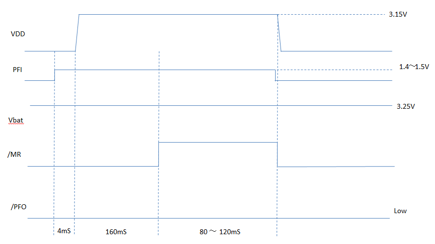
    Please refer to follows for the movement of the signal.

    time       -0 ms           +0 ms        160 ms     240 - 280 ms         500 ms          660 ms           800 ms         900+ ms
    VDD     0 V            3.15 V          3.15 V                0 V                  3.15V             3.15V             3.15V                0V
    Vout         0 V            3.15 V          3.15 V                0 V                  3.15V             3.15V             3.15V          3.25V
    PFI           0 V              1.4 V            1.4 V                 0 V                    1.4V                1.4V              1.4V                0V
    Vbat    3.25 V           3.25 V          3.25 V          3.25 V                  3.25V               3.25V           3.25V          3.25V
    /RST        0                     0                   0                    0                           0                       0                    1                  0
    /MR          0 V                 0 V            Pullup              0 V                       0 V                Pullup         Pullup              0 V
    /PFO        0 V                 0 V               0 V                 0 V                       0 V                   0                Pullup             0 V

    /PFO is 0V    --- Other devices go for a drive when /RST is 0.

    There are other questions.
    >4. Connect VDD to power supply (VDD > VIT) and keep connected for 5 ms < t < 35 ms

    This condition is once effective after VDD rise up?

    Thanks, Masami M.

  • Hi Masami-san,

    Thank you for updating the table.

    I'll try to replicate your circuit. Could you send me a scope shot as well as the schematic of the TPS3619 for comparison? 

    The condition is effective after the rising edge of VDD together with PFI. I will be able to provide more information as soon as I have a scope shot.

    Best regards,

    Nicolás


  • Hi, Nicolas-san,

    Thank you for your reply and answer.
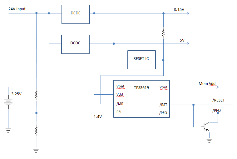
    I list the figure of the schematic of the TPS3619 for comparison.


    Thanks, Masami M.

  • Hi Masami-san,

    Thank you for the schematic.


    I could not replicate the states you send me (see below).

    But since your PFI Pin is connected to VDD, it is possible that you are entering into the "Battery Freshness Seal". You probably reach the condition 3 (VDD = PFI)  at some point powering up the DCDC. 

    If you have a scope shoot you could provide me, I could compare it to the one I took. 

    Best regards,

    Nicolas

  • Hi, Nicolas-san,

    Thank you for your reply.

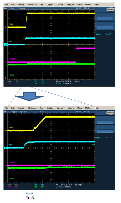
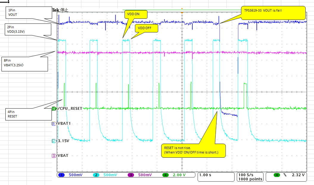
    I send a scope shoot.
    By this scope shoot, the Vbat voltage is 3V.


    Thanks, Masami M.

  • Hi Masami-san,

    Thank you for the scope shots. It helped me to narrow down the issue. 

    I managed to reproduce your signals:

    The problem seams to be the "Power-up reset voltage" (See Datasheet page 3). You need to keep the voltage over 0.4V to maintain a defined output. If you fall under this voltage the device will be in a undefined status, what means that the output can go high or low. (see Figure 13 of the datasheet down below)

    If the part is maintained in a defined state Vout should not go down to 0V. (See scope shot below)

    It is as well recommended to maintain the slew rate for VDD and Vbat  <1V/µs.

    If this solved the issue please let me know. (Verifying the answer is enough) 

    Best regards,

    Nicolás


  • Hi, Nicolas-san,

    Thank you for your reply.

    However, if /RST signal does rise, the phenomenon does not occur.
    When /RST does not do rise, the phenomenon occurs.
    Is this the same phenomenon?

    >It is as well recommended to maintain the slew rate for VDD and Vbat <1V/μs.

    Is this a meaning that a fall time of VDD should be slower than 1V/uS?
    A fall and rise time of VDD are later than 1V/uS, in customer's system.

    Thanks, Masami M.

  • Hi Masami-san,

    Thank you for your answer.

    I did test the device under following conditions. PFI is not displayed but is just divided down from VDD with resistances. The slew rates are 0.9V/µs.

    I run the test 20 times and /RST did always rise up (see scope shot below).

    Since the device is entering the marked state on "table 1" of the datasheet (see below), the output of /RST is behaving as expected. 

    I only saw the rise time of the scope shot you sent me. This one seams to be with in the recommendation. Please be aware the slew rate counts for all rising and falling edges.

    Can you send me a scope shot of an example were /RST does not rise?

    Best regards,

    Nicolás


  • Hi, Nicolas-san,

    Thank you for your reply.

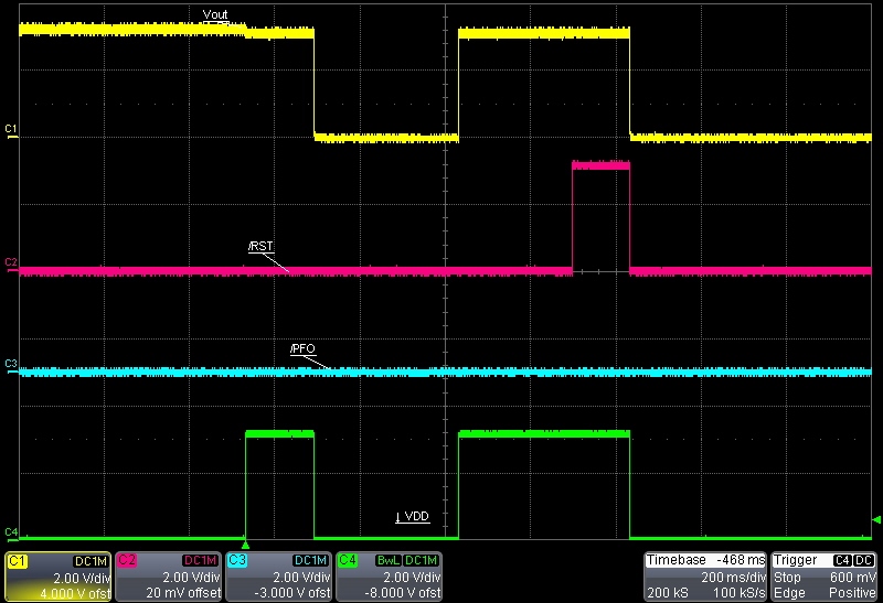
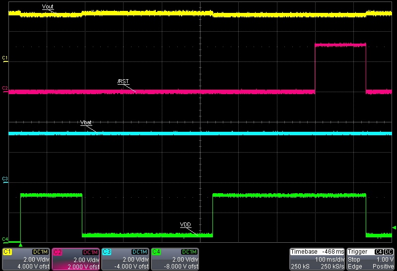
    Please refer to the following figures.
    Vout is not output when VDD's On/Off time is short.
    Vout is output when VDD's On/Off time is long.

    Thanks, Masami M.

  • Hi Masami-san,

    Thank you for your fast reply.

    The delay for the reset signal to rise is is defined as following:

    As such, VDD must be greater than Vit +0.2 V for 100ms (typ) or longer in order for /RESET to go logic high.  From the scope shot it is difficult to tell, but it looks like the VDD pulse is shorter than the ones that did trigger /RESET to go high.

    To rule out the slew rate, could you provide us a scope shot of the falling edge of Vdd?

    Best regards,

    Nicolás

  • Hi, Nicolas-san,

    Thank you for your reply.

    Please try it in the following timings.

    In addition, the all quantity does not produce even the system of the customer.

    The ratio is about 10%.

    Thanks, Masami M.

  • Hi Masami-san,

    Since we don't have your exact system on site, I would kindly ask you to send us a zoom out scope shot of the marked situation below with but instead of measuring Vbat on channel 3 to measure /MR.

    Best regard,

    Nicolás


  • Hi, Nicolas-san,

    Thank you for your reply.

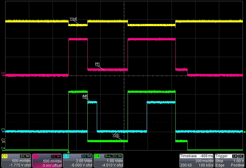
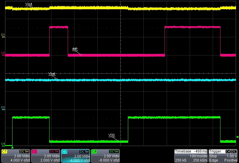
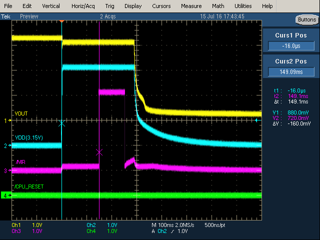
    I show the measurement wave pattern which adds /MR signal, and spread.


    Thanks, Masami M.

  • Hi Masami-san,

    Thank you for the scope shoot.

    Regarding the information you provided me, it looks like you are indeed entering the battery refreshment seal (see the four steps below):

    Regarding the timing of step four:
    The time was set to a maximum of 35ms to ensure that the /RST does not rice (td(min) = 60ms).  Then if this would happen the flag for the “Battery refreshment seal” would be erased.

    Regarding the /RST:
    For the /RST to rise Vdd and /MR need to be at logical high (typ. 100ms, recommended > 140ms). Can you maintain the /MR signal high for >140ms and see if the Vout drop still occurs?

    Please excuse the long exchange. I did not want to jump to conclusions.

    Best regards,

    Nicolas

  • Hi, Nicolas-san,

    Thank you for your answer.

    I would like confirmation.
    - Technique to start a seal mode surely:
    1. Connect VBAT (VBAT > VBAT min)
    2. Ground PFO
    3. Connect PFI to VDD (PFI = VDD)
    4. Connect VDD to power supply (VDD > VIT) and keep connected for 5 ms < t < 35 ms

    -Technique not to start a seal mode surely.
    1. Do not connect VBAT (VBAT > VBAT min), during VDD start up after less than 35mS.
    or
    2. Do not PFO to Low level, during VDD start up after less than 35mS.
    or
    3. Do not Connect PFI to VDD level, during VDD start up after less than 35mS.

    Is this right?

    Thanks, Masami M.

  • Hi Masami-san,

    Yes that is what the datasheet says. 

    I would go with you first option (Vbat < Vbat_min during startup) or ensure the 140ms on-time for /MR and VDD, so that /RST rises for sure, what would erase the battery freshness seal.

    Best regards,
    Nicolas


  • Hi, Nicolas-san,

    Thank you for your reply.
    I explained the contents of the answer to the customer.

    Thanks, Masami M.

  • Hi Masami-san,

    You're welcome. I hope I could help you.

    Best regards,
    Nicolás