This thread has been locked.

If you have a related question, please click the "Ask a related question" button in the top right corner. The newly created question will be automatically linked to this question.

Adjustable threshold/hysteresis design using TPS3701

Other Parts Discussed in Thread: TPS62125, LM2596, TPS3806, TPS3701

Hi,

  I was looking at TPS62125, as the only regulator I could find that allowed adjustable threshold and hysteresis, but its output current is too limited.

  I am trying to design a similar thing for another regulator with higher output current capabilities, say LM2596. I am also limited on space, so I am looking for a one-chip solution. You may have something else that works better. Please let me know. Also, I want something that can accept a Vin up to 30v.

  What I am trying to achieve is (Baiscally a big hysteresis):

1) If regulator is disabled (When system is starting), and input voltage is above 12.16v, then regulator is enabled.

2) Once enabled, if input voltage drop below 9.6 volt, then regulator is disabled.

I also like this to happen very slow (Like with few seconds delay). Wehre can I put some capacitors to slow this down?

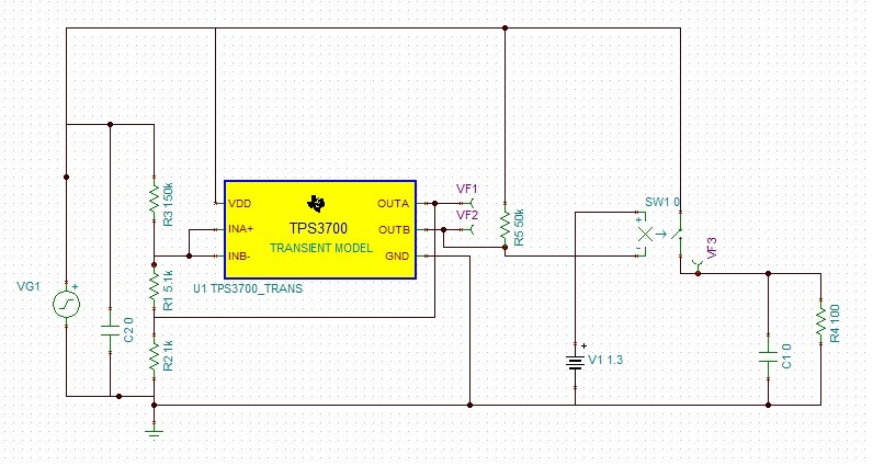
  • For start, this is a basic design I came up with:

  • Hi Morteza,

    For such a wide hysteresis, you could look at the TPS3806, which has dual voltage detectors and with adjustable hysteresis. The lower threshold (LSENSE) and higher threshold (HSENSE) can both be set using resistor dividers – you will need to make sure your input voltage is within the recommended operating conditions found in the datasheet, or else you will risk damaging the device.

    Regards,

    Yuanhao

  • I saw what you mentioned. As you said, it's input is the concern. I would typically work in 12v range, but transient of up to 30 is possible.

    Looks like what the TPS3806 is doing internally, though, is similar to what I am trying to do with TPS3701.

    So, there are 2 branches now:

    1. Is there a way TPS3806 can get its supply from somewhere with big transients with some voltage divider, considering its usage is uA anyways.

    2. Is the TPS3701 design correct, wrong, it could be improved.

  • Hi Morteza,

    One way to deal with the input problem would be to use a buck to step down the voltage, and then an LDO in series to smooth out any transients. Or you could just step down the voltage using a resistor divider network, and then an LDO to smooth out transients. The TPS3701 would not work because it has an internal hysteresis of 5mV, so it would not handle the conditions you’re thinking of.

    Regards,
    Yuanhao
  • Hi Yuanhao,

    I have to diagree with you. True that internal hysteresis of TPS3701 does not work, but it is possible in one way or another to use one output of 3701 as a feedback switch. I need to direct your attention to the fact that I am using output A to short the 1.5k ohm resistor. In fact, TPS3806 is doing exactly the same thing internally, i.e. turning a switch on or off allowing the selection of two different resistance values.

    MAXIM and Analog Devices have guides for this, and how we can create big hysteresis values through fets or transistors. Simply saying that TPS3701 cannot be used, I believe, is not right, and the matter is that is it designed correctly, or is it a better design adding even another LDO for supplying the supervisor chip of another regulator OR designing a bunch of resistors around a supervisor chip that can handle large inputs itself. Even if the TPS3701 design would work in theory, is there situations it may bounce in output A, causing the feedback to become unstable? Overall, saying that is it is impossible doing so with TPS3701 doesn't seem to be very correct.

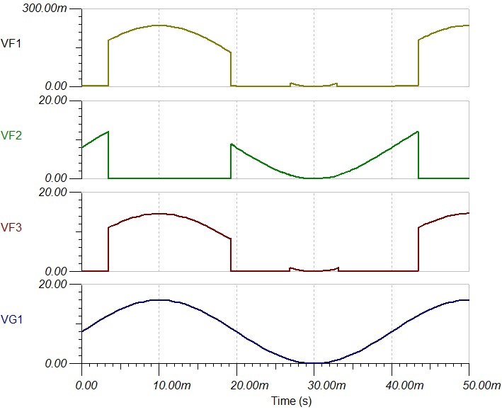
  • Here is some proof that theory works. Hysteresis in this simulation is about 3 volts. The point is though what happens outisde simulation, when battery/load is not perfect.

  • Hi Morteza,


    I apologize for misreading your schematic – upon further review, I believe your circuit should work in theory. However, since the part was not designed, tested, or characterized for your operation, I suggest you rigorously test your circuit. Make sure to keep voltage and currents within the limits in the datasheet.


    Regarding your concerns about input transients, you could use an LDO/buck circuit to regulate the voltage.


    Regards,

    Yuanhao