This thread has been locked.

If you have a related question, please click the "Ask a related question" button in the top right corner. The newly created question will be automatically linked to this question.

TPS3820-50-Q1: WDI pulled down with a resistor instead of floating

Part Number: TPS3820-50-Q1

Hi, team,

My customer met one question about TPS3820-50-Q1.

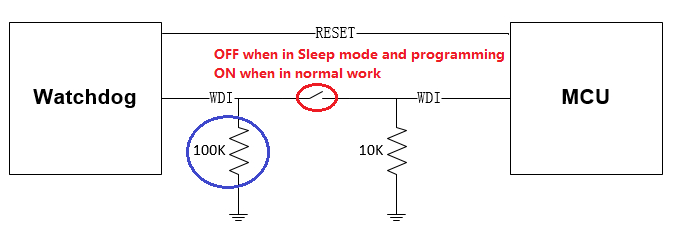
They use a switch to control the WDI and MCU connection, when in programming the switch is OFF, when in normal work the switch is ON. Thus when in programming, TPS3820 will not reset MCU.

They are concern about the noise in Automotive system, so they do not like WDI pin to be floating, and a 100k resistor is added from WDI to GND by the device.

I checked the TPS3820-50-Q1 block diagram, if WDI is floating, internal Auto-reset oscillator will generate signal to transition detector through a 40k resistor.

My question is as below.

1. Is customer's 100k pull-down resistor connection ok if WDI is not floating?

2. What is the output voltage of Auto-reset oscillator? What is the voltage threshold of Transition detector?

3. Customer tested that if the WDI-GND resistor is >36k and Switch OFF, TPS3820-50-Q1 will not output reset signal. This should be related with the WDI pin voltage.

4. About the 100k resistor to GND, could you give more comments about the other risk to system?

Thanks.

Johnny

  • Hi Johnny,

    1. I also tested 100k on my EVM and found that it didn't release reset. It might be ok, but I suggest the customer to test a few boards at high/low temp, to include for tolerance on the resistor and in the device. This isn't something we spec or characterize.

    2. I'm not sure about this circuit. Let me look in to it.

    3. Like (1), I suggest to measure across temp and on a couple other units. Based on your results, I would guess 100k is high enough not to cause reset, but some more data points would be helpful.

    4. I don't see any other risk, besides possible causing the device recognizing a GND and therefore issuing a regular reset. The 100k will of course reduce the effective pull-down resistance in normal mode, but compared to the 10k I don't think it will have any significant effect.

    Regards,
    Karl
  • Karl,

    Thanks for reply. Looking forward to your reply for below question.

    2. What is the output voltage of Auto-reset oscillator? What is the voltage threshold of Transition detector?

    Thanks.

    Johnny

  • Hi Johnny,

    I took some waveform captures of the WDI pin with VDD=5V.  It looks like the 40k plus external resistance creates a resistor divider on the WDI pin, and that resistor divider value charges up an internal capacitor.  As soon as the transition detector detects a high voltage (in this case ~2.3V, but this could be up to VDD*0.7=3.5V), then it triggers the watchdog and therefore does not reset.  For example, with 100k resistor, you have 40k and 100k divider causing 3.57V to be applied to the capacitor.  With 33k resistor, you have 2.26V (and therefore the very curved waveform), and with 4.7k resistor you have 0.5V, which does not cause any transition.

    WDI pin open:


    WDI pin with 100k to GND:

    WDI pin with 33k to GND:

    WDI pin with 4.7k to GND:

    Therefore you might want to have the customer increase 100k, since this is right on the boundary of 3.5V.  Given the tolerance of the 100k, and the tolerance of the 40k, you might want the customer to do 200kohm to be safe.  And as I mentioned before, the customer needs to do some validation testing on their board.  We’ve only done validation and characterization testing with floating input, so anything else needs to be tested by the customer.

    Regards,
    Karl