This thread has been locked.

If you have a related question, please click the "Ask a related question" button in the top right corner. The newly created question will be automatically linked to this question.

TPS3890: Using TPS3895A to detect low voltage

Part Number: TPS3890
Other Parts Discussed in Thread: TPS3898, , TPS3896, TPS3895, TPS3897

Hi everyone,

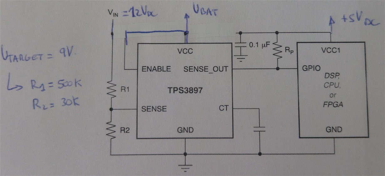
I'm trying to use the TPS3895A (SENS_OUT: active high) in order to detect low voltage in a voltage input of 12 Volts. My Theoretical Vtarget is 9 Volts, so with R1 = 500K and R2 = 30K Vtarget = 8.83 volts.

I've read in the datahseet that Vsens <= 6.5Volts. In my case Vsens = R2/(R1+R2) * 12 = 30 / 530 *12 = 0.6792 Volts

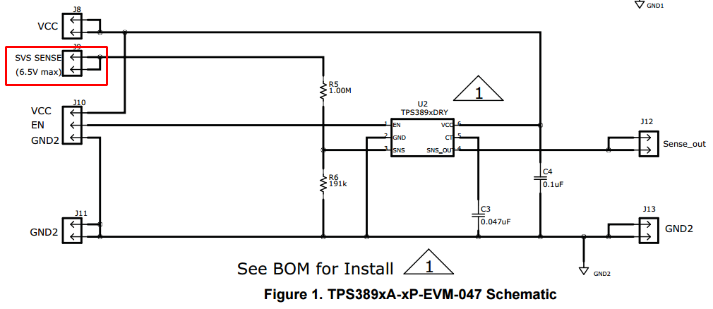
But I was reading the document: User's Guide - SLVU524A–August 2011–Revised September 2011 - TPS389xA-xP-EVM047 Evaluation Modules and it seems to be that the maximum voltage in the Jp pin  is 6.5Volts:

Does anyone know if my configuration is right? or I can't use an input of 12 Volts in the resistance network (R1/R2).

Best regards.

  • Oscar,

    Couple things I need to comment on.

    1. TPS3890 is not in the TPS389x family (TPS3895, TPS3896, TPS3897, TPS3898). Sorry for the confusion there.

    2. 6.5V max rating is for the SENSE pin. This means you can detect any voltage so long as it is divided down with resistor divider so that the voltage at the SENSE pin is less than 6.5V. The EVM might be configured to accept only 6.5V at SVS SENSE but you can change those resistors on the EVM so that the voltage at SVS SENSE can be higher. The voltage at which the voltage at SENSE triggers the output is in the datasheet as V_IT+ and is 0.5V typical. So you want to divide your input voltage down so that if it is any lower, the voltage at SENSE will be lower than 0.5V - hysteresis (and to never exceed 6.5V).

    3. 12V going to a resistor divider of R1 = 500k, R2 = 30k provides 0.679V at SENSE. This means the output will be active and "high". If your 12V input drops to 8.745V, then your divider will provide 0.495V at SENSE (0.5V for V_IT+ threshold minus 5mV for hysteresis), and this will cause the output to deactivate and drop "low".

    Please let me know if this makes sense or if you need additional support. Thanks!

    -Michael
  • Hi Michael,

    Thank you in advance for help and quick reply.

    I was reading the datasheet and I think I am going to need the TPS3896A. ENABLE (Active Low) and OUTPUT(ACTIVE LOW, push-pull) instead of the TPS3895A, because I think I understood badly the way of working the SENS_OUT signal.

    The correct way of working is: when the Vin > Vatrget, SENS_OUT is activated (I thought that SENS_OUT signal was activated when Vin <= Vtarget), so If I choose the TPS3896x:

    i) When Vin > Vtarget (8.745Volts) SENS_OUT = Low.
    ii) When Vin <= Vtarget (8.745Volts) SENS_OUT = High.

    Am I right?

    Best regards.

  • Hi Michael,

    I've just received my TPS389xA-xP-EVM-047, and I've got some questions related to the J9 connector SVS SENS with the label 6.5V Max.

    According to the datasheet, the pin SENSE has to be <= 6.5 Volts. But I don't understand why appears the label 6.5V Max.
    R1 = 1M and R2 = 161K so I've a place 10 Volts in the pin SVS SENSE the voltage in the pin SENSEN is going to be 1.39 volts.
    So I don't understand the warning in the connector J9 SVS SENSE.

    Do you know if I am right?

    I would like to confirm this before to connect anything in order not to damage anything.

    Best regards.

  • Oscar,

    1. When you say Vin, please use term V_SENSE. The SENSE input is what causes the SENSE_OUT output to change.

    2. Active-low for a SENSE_OUT device means when VCC is high AND SENSE is high, then SENSE_OUT is active and low. If SENSE is low, then SENSE_OUT is inactive meaning high.

    Active-high for a SENSE_OUT device means when VCC is high AND SENSE is high, then SENSE_OUT is active and high. If SENSE is low, then SENSE_OUT is inactive meaning low.

    3. SENSE voltage can be divided down using resistor divider to the SENSE pin. The threshold rising is 0.5V. Since your resistor divider provides 1.39V at SENSE, this is OK since it is less than 6.5V. The device will become inactive when SENSE voltage drops below 0.5 - hysteresis so 0.495V.

    You will only damage device if SENSE voltage at the device (after the monitored voltage is divided to SENSE) is above the ABS MAX found in the datasheet.

    Does this answer you question?

    -Michael

  • Ok Michael,

    Thaks in advance for your help and for your quick reply.

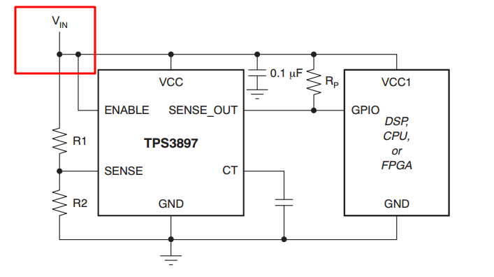
    1.- I saw this picture in the datasheet and this is the reason I used the term VIN. But from now on I'm going to use the term V_SENSE.

    2º.- Everything else understood, but I've just received my TPS389xA-xP-EVM-047, and I've got some questions related to the J9 connector SVS SENS with the label 6.5V Max. But I don't understand why appears the label 6.5V Max, due to the fact that, R1 = 1M and R2 = 161K so If the pin SVS SENSE = 10V, that is to say, V_SENSE = 10 V, the voltage in the pin SENSE is going to be 1.39 volts. So I don't understand the warning in the connector J9 SVS SENSE (6.5V Max). Could you explain me that?

    Best regards

  • Oscar,

    1. The reason I say use SENSE instead of Vin is because notice in the figure you posted above, Vin connects to SENSE, ENABLE, and VCC so it can get confusing. When you say SENSE or V_SENSE then I know you are talking about the voltage at the SENSE pin. Thanks!

    2. The label "6.5V Max" refers to the voltage at the SENSE pin. You said yourself that with input voltage (Vin) of 10V then V_SENSE (voltage at the SENSE pin) is only 1.39V so this is ok. As long as V_SENSE (voltage at the sense pin on the device) is less than 6.5V, then you are all good! The reason the connector says 6.5V Max as a warning because it is expected that people will change the resistors in the resistor divider so we want to remind users that SENSE pin voltage has a 6.5V max spec. Also, using the above figure, the limitation won't be on SENSE pin due to the resistor divider but the limit will be on ENABLE and VCC pins since these are directly connected to Vin in the above diagram. It is important that all pins don't exceed their recommended operating conditions.

    Let me know if you have any more questions!

    -Michael
  • Understood. Thank you very much.