Can you please assist with my UCD90160 Configuration Programming Issue:
- I created the project.xml program file for the parts (we have two on the board, sharing the same I2C bus/programming connector) using the TI Fusion Digital Power Designer software in Offline mode.
- Now that we have the board, I use the online version of the tool, and connect to it using the TI USB programming adaptor for these parts. It sees the two parts in the i2c bus, and I program them, everything seems good.
- I use one GPI pin as an input to control a number of GPIO’s. These are configured as outputs which I’m going to use as enables for other regulators. My design is that when the GPI pin goes high, a number of GPOs will go high, in a sequence, with a short delay between each. This works fine after just programming with the TI software.
- However, after I power cycle the board, I re-check things, the parts appear to be programmed, in that all the rails are labeled correctly, the GPO’s logic programs appear correct, but when I toggle the GPI input pin, the GPO’s all stay low, as if they’re not programmed.
- If I reconnect with the TI software and change the logic program on one of the GPO’s, say from an OR gate to a NOR gate, commit it to the device, etc. now it works, i.e. as a NOR gate. I see it essentially invert the GPI signal. Change it back to the OR gate, commit, etc. now it tracks the GPI as I want it to.
- Power cycle again, and its lost it again.
It’s like the logic for the GPO’s doesn’t work after a power on, only after being programmed. I hope this isn’t how these work. The part is the UCD90160.
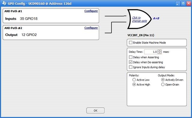
Here is a snapshot of the screen from with TI’s software where I put a simple logic program for one of the GPO’s I want to use:
So it simply should track the GPI input (pin35, GPIO18) but only does so right after programming the part. Once powering down and back on again, if I check the logic it looks like the screenshot, but the GPO pin just doesn’t work again, until manually programming it again.
Thanks,
Rob

